PM-1004-R20 PC/104 4-Port RS-232/ 422/485 Module User Manual Version 2.0 January 10, 2006 @Copyright 2006 by ICP Electronics Inc. All Rights Reserved.
Copyright Notice The information in this document is subject to change without prior notice in order to improve reliability, design and function and does not represent a commitment on the part of the manufacturer. In no event will the manufacturer be liable for direct, indirect, special, incidental, or consequential damages arising out of the use or inability to use the product or documentation, even if advised of the possibility of such damages.
Table of Contents CHAPTER 1. INTRODUCTION..................4 1.1 SPECIFICATIONS..........................................................4 1.2 PACKAGE CONTENTS .....................................................5 CHAPTER 2. INSTALLATION ..................6 2.1 HARDWARE INSTALLATION ..............................................6 2.2 BOARD LAYOUT ..........................................................7 2.3 INTERRUPT STATUS ADDRESS SETTING .................................9 2.3.
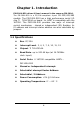
Chapter 1. Introduction PM-1004-R20 driver & User’s manual is the same as PM-1004. The PM-1004-R20 is a PC/104-compliant 4-port RS-232/422/485 module. The PM-1004-R20 has a high performance serial I/O chip TI TL16C554A on board. Its UART is compatible with the 16C550. The PM-1004-R20 provides two ways of interrupt control mechanism - shared or independent IRQ. Besides, its IO address and interrupt status address are also selectable by jumpers. 1.1 Specifications Bus: PC/104.
1.2 Package Contents The following items will be found in the packaged contents: 1 x PM-1004-R20 1 x Serial port RS-232 cable (40 pin, 4 DB-9 ) 1 x RS-422/485 cable (16 PIN, 4 DB-9 ). 1 x DRIVER CD-ROM 1 x User manual If any of these items are missing or damaged, please contact the dealer who you purchased the product from. Be sure to save the shipping materials and carton in case you want to ship or store the product in the future.
Chapter 2. Installation This chapter describes how to install the PM-1004-R20. 2.1 Hardware Installation To install the PC/104 modules, please follow the instructions below. Note: Please ground yourself to remove any static charges before touching your PM-1004-R20. You can do it by using a grounded wrist strap at all times or by frequently touching any conducting materials that is connected to the ground. 1. Turn the power off 2. Plug the PC/104 module into the connectors on the CPU card. 3.
2.
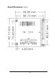
Board Dimension (mm) 8
2.
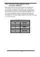
2.3.1 Interrupt Status Register Setup (S1,Vector Address) When data arrives at one of the four ports, it will generate an interruption in the interrupt register. The PC software can read this, and identify immediately which port generated the interruption. This saves time, and makes programming easier. When a data bit of the interrupt status register is set to 1, the corresponding channel is selected to generate an interruption. If the bit is 0,then no interruption is generated.
2.
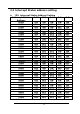
300-307H 308-30FH 310-317H 318-31FH 320-327H 328-32FH 330-337H 338-33FH 340-347H 348-34FH 350-357H 358-35FH 360-367H 368-36FH 370-377H 378-37FH 380-387H 388-38FH 390-397H 398-39FH 3A0-3A7H 3A8-3AFH 3B0-3B7H 3B8-3BFH 3C0-3C7H 3C8-3CFH 3D0-3D7H 3D8-3DFH 3E0-3E7H 3E8-3EFH 3F0-3F7H 3F8-3FFH *: Default OFF OFF OFF OFF OFF OFF OFF OFF OFF OFF OFF OFF OFF OFF OFF OFF OFF OFF OFF OFF OFF OFF OFF OFF OFF OFF OFF OFF OFF OFF OFF OFF ON ON ON ON ON ON ON ON ON ON ON ON ON ON ON ON OFF OFF OFF OFF OFF OFF OFF OFF OFF
COM Port I/O Address COM Port I/O address COM1 Base Address + 00H COM2 Base Address + 08H COM3 Base Address + 10H COM4 Base Address + 18H 2.
Chapter 3. Connection This chapter describes how to connect peripherals, switches and indicators to the PM-1004-R20 board. 3.1 RS-232/422/485 Connector The serial ports are high speed NS16C550 compatible UART with Read/Receive 16 byte FIFO. CN5(RS-232): COM1 ~ COM4 Serial Port Connectors.
CN3 (RS-422/485): COM1 ~ COM4 Serial Port Connectors.
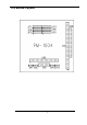
3.2 PC/104 Expansion Bus The PC/104 expansion bus on the enables you to attach it to the PC/104 slot of a target system. The PC/104 bus has already become an industrial embedded PC bus standard, so you can easily install thousands of PC/104 modules from hundreds of vendors in the world. There are two types of connectors on this board -- PC/104-64 and PC/104-40.
PC/104-64 Connector PIN NO PIN NO DESCRIPTION A1 IOCHCK# B1 A2 SD7 B2 A3 SD6 B3 A4 SD5 B4 A5 SD4 B5 A6 SD3 B6 A7 SD2 B7 A8 SD1 B8 A9 SD0 B9 A10 IOCHRDY B10 A11 AEN B11 A12 LA19 B12 A13 LA18 B13 A14 LA17 B14 A15 LA16 B15 A16 LA15 B16 A17 LA14 B17 A18 LA13 B18 A19 LA12 B19 A20 LA11 B20 A21 LA10 B21 A22 LA9 B22 A23 LA8 B23 A24 LA7 B24 A25 LA6 B25 A26 LA5 B26 A27 LA4 B27 A28 LA3 B28 A29 LA2 B29 A30 LA1 B30 A31 LA0 B31 A32 GND B32 17 DESCRIPTION GND IRSTDRV VCC IRQ9 -5V N/C -12V ZWS +12V GND SMEMW# SMEMR# IOW#