
User guide

NANO-9452 EPIC Motherboard
Page 42
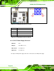
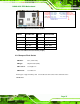
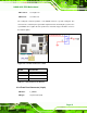
CN Location:
See Figure 4-10
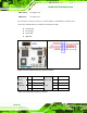
CN Pinouts:
See Table 4-10
The front panel connector connects to external switches and indicators to monitor and
controls the motherboard. These indicators and switches include:
Power button
Reset button
Power LED
HDD LED
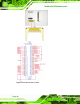
Figure 4-10: Front Panel Connector Pinout Locations
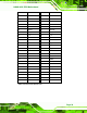
FUNCTION PIN DESCRIPTION FUNCTION PIN DESCRIPTION
1 PWRBTSW- 2 VCC Power
Button
3 Ground
Power LED
4 Ground
5 VCC 6 SYSRST- HDD LED
7 HDD LED-
Reset
8 GND
Table 4-10: Front Panel Connector Pinouts