
Instruction Manual


NANO-945GSE2
Page 19
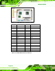
Figure 3-6: Panel Backlight Connector Pinout Locations
PIN NO. DESCRIPTION
1 LCD Backlight Control
2 GROUND
3 +12V
4 GROUND
5 BACKLIGHT Enable
Table 3-6: Panel Backlight Connector Pinouts
3.3.5 Battery Connector
CN Label: BT1
CN Type:
2-pin wafer (1x2)
CN Location:
See Figure 3-7
CN Pinouts:
See Table 3-7
The battery connector is connected to a backup battery. The battery connector is also
used to reset the CMOS memory if the incorrect BIOS settings have been made and the
system cannot boot up.