
Instruction Manual


NANO-945GSE2
Page 24
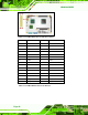
Power button
Reset
Power LED
HDD LED
Figure 3-11: Front Panel Connector Pinout Locations (8-pin)
FUNCTION PIN DESCRIPTION FUNCTION PIN DESCRIPTION
1 PWR_BTN 2 VCC5 Power Button
3 GND
Power LED
4 GND
5 HDD_LED+ 6 SYSRST- HDD LED
7 HDD_LED-
Reset
8 GND
Table 3-11: Front Panel Connector Pinouts (8-pin)
3.3.10 Infrared Interface Connector (5-pin)
CN Label: IR1
CN Type:
5-pin header (1x5)
CN Location:
See
6Figure 3-12
CN Pinouts:
See
6Table 3-12
The infrared interface connector supports both Serial Infrared (SIR) and Amplitude Shift
Key Infrared (ASKIR) interfaces.