
Owner manual


Table Of Contents
- NANO-LX EPIC SBC User Manual
- 1 Introduction
- 2 Detailed Specifications
- 2.1 Overview
- 2.2 Dimensions
- 2.3 Data Flow
- 2.4 CPU Support
- 2.5 System Chipset
- 2.5.1 GeodeLink™ Interface Unit
- 2.5.2 AMD® Geode™ CS5536 ATA-6 Controller
- 2.5.3 AMD® Geode™ CS5536 Audio Codec 97 (AC’97) Controller
- 2.5.4 AMD® Geode™ CS5536 Flash Interface
- 2.5.5 AMD® Geode™ CS5536 USB Controller
- 2.5.6 AMD® Geode™ CS5536 Serial Communications
- 2.5.7 AMD® Geode™ CS5536 Real Time Clock
- 2.5.8 BIOS
- 2.6 GeodeLink™ PCI Bridge
- 2.7 Environmental and Power Specifications
- 3 Unpacking
- 4 Connectors and Jumpers
- 4.1 Peripheral Interface Connectors
- 4.2 Internal Peripheral Connectors
- 4.2.1 ATX Connector
- 4.2.2 ATX Power Button
- 4.2.3 Audio CD-In Connector
- 4.2.4 Audio Connector
- 4.2.5 Battery Connector
- 4.2.6 Compact Flash Connector
- 4.2.7 Digital Input Output Connector
- 4.2.8 Fan Connector
- 4.2.9 FDD Connector
- 4.2.10 IDE Interface Connector
- 4.2.11 Inverter Connector
- 4.2.12 IrDA Connector
- 4.2.13 Keyboard/Mouse Connector
- 4.2.14 LED Power Connector
- 4.2.15 LVDS LCD Panel Connector
- 4.2.16 Parallel Port Connector
- 4.2.17 PC/104-Plus Connector
- 4.2.18 Power Connector
- 4.2.19 Power Input Connector
- 4.2.20 Reset Button Connector
- 4.2.21 SATA Drive Ports
- 4.2.22 Serial Communications Connector
- 4.2.23 TFT TTL LCD Connector
- 4.3 External (Rear Panel) Connectors
- 5 Installation and Configuration
- 6 Award BIOS Setup
- 7 Software Drivers
- A BIOS Configuration Options
- B Watchdog Timer
- C Address Mapping
- D External AC’97 Audio CODEC
- E ALi® RAID for SATA
- F Connecting an ATX Power Supply
- G Index
NANO-LX EPIC SBC
Step 1: Locate the DB-9 connector. The location of the DB-9 connector is shown in
Chapter 3.
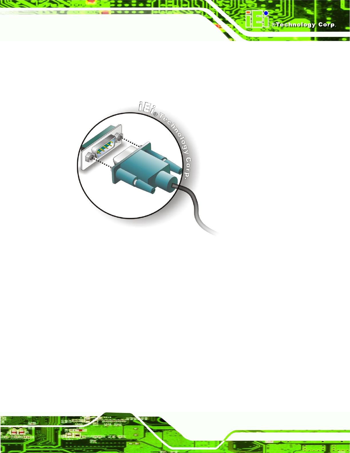
Step 2: Insert the serial connector. Insert the DB-9 connector of a serial device into
the DB-9 connector on the external peripheral interface. See
Figure 5-15.
Figure 5-15: Serial Device Connector
Step 3: Secure the connector. Secure the serial device connector to the external
interface by tightening the two retention screws on either side of the connector.
Step 0:
5.9.4 USB Connection (Dual Connector)
The external USB Series "A" receptacle connectors provide easier and quicker access to
external USB devices. Follow the steps below to connect USB devices to the NANO-LX.
Step 1: Locate the USB Series "A" receptacle connectors. The location of the USB
Series "A" receptacle connectors are shown in Chapter 3.
Step 2: Insert a USB Series "A" plug. Insert the USB Series "A" plug of a device into
the USB Series "A" receptacle on the external peripheral interface. See
Figure
5-16
. Step 0:
Page 111