
Owner manual


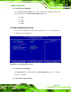


Table Of Contents
- NANO-LX EPIC SBC User Manual
- 1 Introduction
- 2 Detailed Specifications
- 2.1 Overview
- 2.2 Dimensions
- 2.3 Data Flow
- 2.4 CPU Support
- 2.5 System Chipset
- 2.5.1 GeodeLink™ Interface Unit
- 2.5.2 AMD® Geode™ CS5536 ATA-6 Controller
- 2.5.3 AMD® Geode™ CS5536 Audio Codec 97 (AC’97) Controller
- 2.5.4 AMD® Geode™ CS5536 Flash Interface
- 2.5.5 AMD® Geode™ CS5536 USB Controller
- 2.5.6 AMD® Geode™ CS5536 Serial Communications
- 2.5.7 AMD® Geode™ CS5536 Real Time Clock
- 2.5.8 BIOS
- 2.6 GeodeLink™ PCI Bridge
- 2.7 Environmental and Power Specifications
- 3 Unpacking
- 4 Connectors and Jumpers
- 4.1 Peripheral Interface Connectors
- 4.2 Internal Peripheral Connectors
- 4.2.1 ATX Connector
- 4.2.2 ATX Power Button
- 4.2.3 Audio CD-In Connector
- 4.2.4 Audio Connector
- 4.2.5 Battery Connector
- 4.2.6 Compact Flash Connector
- 4.2.7 Digital Input Output Connector
- 4.2.8 Fan Connector
- 4.2.9 FDD Connector
- 4.2.10 IDE Interface Connector
- 4.2.11 Inverter Connector
- 4.2.12 IrDA Connector
- 4.2.13 Keyboard/Mouse Connector
- 4.2.14 LED Power Connector
- 4.2.15 LVDS LCD Panel Connector
- 4.2.16 Parallel Port Connector
- 4.2.17 PC/104-Plus Connector
- 4.2.18 Power Connector
- 4.2.19 Power Input Connector
- 4.2.20 Reset Button Connector
- 4.2.21 SATA Drive Ports
- 4.2.22 Serial Communications Connector
- 4.2.23 TFT TTL LCD Connector
- 4.3 External (Rear Panel) Connectors
- 5 Installation and Configuration
- 6 Award BIOS Setup
- 7 Software Drivers
- A BIOS Configuration Options
- B Watchdog Timer
- C Address Mapping
- D External AC’97 Audio CODEC
- E ALi® RAID for SATA
- F Connecting an ATX Power Supply
- G Index

NANO-LX EPIC SBC
The ECP Mode Use DMA option is only available if the Parallel Port Mode option is set
to ECP mode. Use the ECP Mode Use DMA option to specify the DMA channel the
parallel port must use in the ECP mode.
1
The parallel port uses DMA Channel 1 in ECP mode.
3
(Default) The parallel port uses DMA Channel 3 in ECP mode.
CIR Port Address [Disabled]
Use the CIR Port Address option to enable the CIR port and set the CIR port base
address.
Disabled (Default)
3F8
2F8
3E8
2E8
x CIR Port IRQ [11]
The CIR Port IRQ option is only available if the CIR Port Address option is not disabled.
Use the CIR Port IRQ option to specify an interrupt address for the CIR port. The CIR
Port IRQ options are:
11 (Default)
5
Onboard Serial Port # [XXX]
Use the Onboard Serial Port # option to select the I/O address and IRQ for any additional
onboard serial ports. The Onboard Serial Port # address options are:
Disabled
3F8
2F8
3E8
2E8
Page 144