
Owner manual


Table Of Contents
- NANO-LX EPIC SBC User Manual
- 1 Introduction
- 2 Detailed Specifications
- 2.1 Overview
- 2.2 Dimensions
- 2.3 Data Flow
- 2.4 CPU Support
- 2.5 System Chipset
- 2.5.1 GeodeLink™ Interface Unit
- 2.5.2 AMD® Geode™ CS5536 ATA-6 Controller
- 2.5.3 AMD® Geode™ CS5536 Audio Codec 97 (AC’97) Controller
- 2.5.4 AMD® Geode™ CS5536 Flash Interface
- 2.5.5 AMD® Geode™ CS5536 USB Controller
- 2.5.6 AMD® Geode™ CS5536 Serial Communications
- 2.5.7 AMD® Geode™ CS5536 Real Time Clock
- 2.5.8 BIOS
- 2.6 GeodeLink™ PCI Bridge
- 2.7 Environmental and Power Specifications
- 3 Unpacking
- 4 Connectors and Jumpers
- 4.1 Peripheral Interface Connectors
- 4.2 Internal Peripheral Connectors
- 4.2.1 ATX Connector
- 4.2.2 ATX Power Button
- 4.2.3 Audio CD-In Connector
- 4.2.4 Audio Connector
- 4.2.5 Battery Connector
- 4.2.6 Compact Flash Connector
- 4.2.7 Digital Input Output Connector
- 4.2.8 Fan Connector
- 4.2.9 FDD Connector
- 4.2.10 IDE Interface Connector
- 4.2.11 Inverter Connector
- 4.2.12 IrDA Connector
- 4.2.13 Keyboard/Mouse Connector
- 4.2.14 LED Power Connector
- 4.2.15 LVDS LCD Panel Connector
- 4.2.16 Parallel Port Connector
- 4.2.17 PC/104-Plus Connector
- 4.2.18 Power Connector
- 4.2.19 Power Input Connector
- 4.2.20 Reset Button Connector
- 4.2.21 SATA Drive Ports
- 4.2.22 Serial Communications Connector
- 4.2.23 TFT TTL LCD Connector
- 4.3 External (Rear Panel) Connectors
- 5 Installation and Configuration
- 6 Award BIOS Setup
- 7 Software Drivers
- A BIOS Configuration Options
- B Watchdog Timer
- C Address Mapping
- D External AC’97 Audio CODEC
- E ALi® RAID for SATA
- F Connecting an ATX Power Supply
- G Index
NANO-LX EPIC SBC
WARNING!
The new power adapter cable for the NANO-LX has its “Ground” pin
removed from the 3-pin ATX feature connector. Connecting the power
feature connector cable will destroy the CPU board.
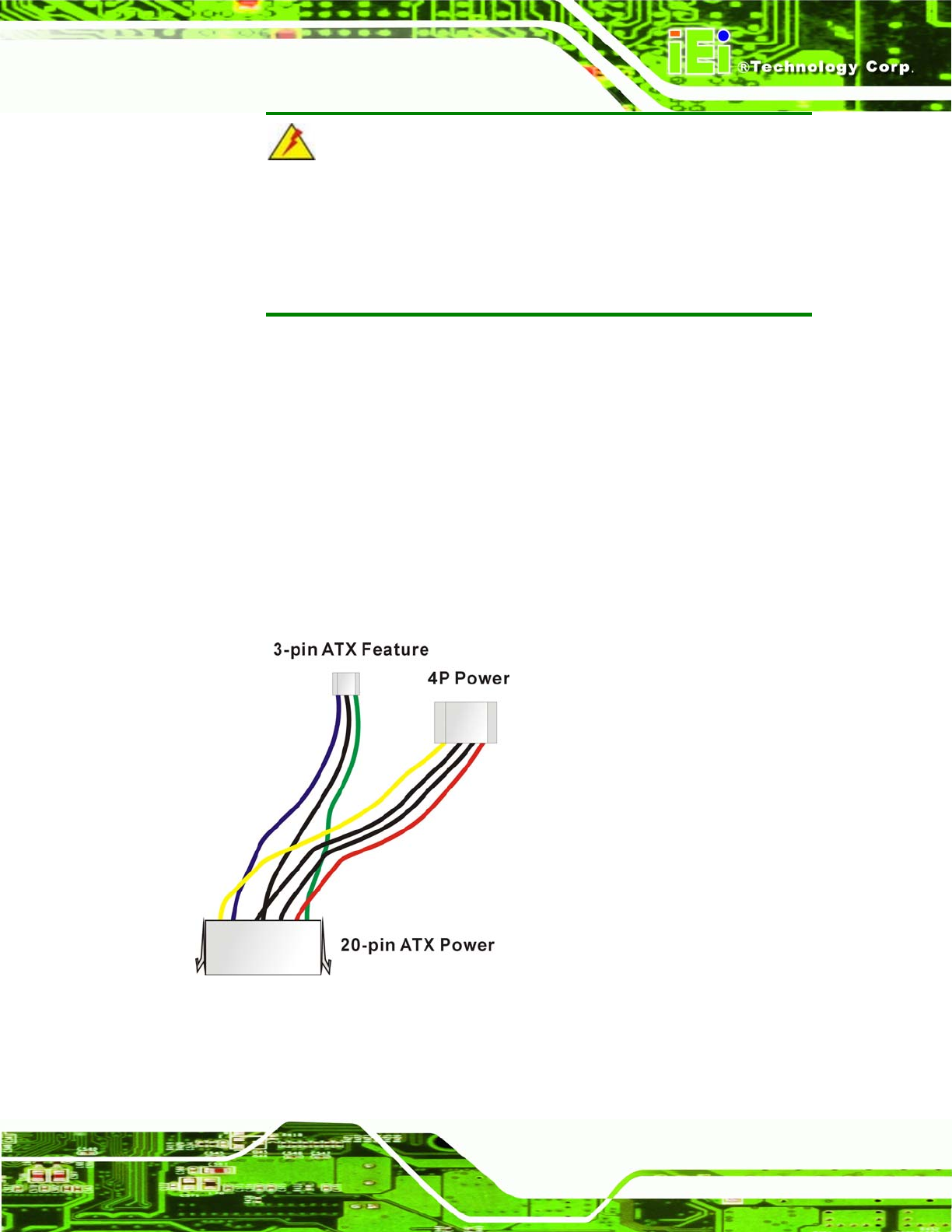
Step 3: Be sure that the standard 4-pin AT power connector is connected to the SBC
power connector (CN2).
Step 4: Connect the optional ATX power cable to the AT power cable using their 4P
power connectors (
Figure F-2).
Step 5: Connect the optional ATX power cable to the SBC ATX connector (CN3) using
the 3-pin ATX feature connector (
Figure F-2).
Step 6: Connect an ATX power button switch to CN5.
Step 7: Connect the 20-pin ATX power connector to an ATX power supply (
Figure F-2).
Figure F-2: ATX Power Adapter Cable
Step 8: Press the power button switch once to turn on the system. To turn off the power
supply press the ATX power switch button for about 4 seconds.Step 0:
Page 227