
Owner manual


Table Of Contents
- NANO-LX EPIC SBC User Manual
- 1 Introduction
- 2 Detailed Specifications
- 2.1 Overview
- 2.2 Dimensions
- 2.3 Data Flow
- 2.4 CPU Support
- 2.5 System Chipset
- 2.5.1 GeodeLink™ Interface Unit
- 2.5.2 AMD® Geode™ CS5536 ATA-6 Controller
- 2.5.3 AMD® Geode™ CS5536 Audio Codec 97 (AC’97) Controller
- 2.5.4 AMD® Geode™ CS5536 Flash Interface
- 2.5.5 AMD® Geode™ CS5536 USB Controller
- 2.5.6 AMD® Geode™ CS5536 Serial Communications
- 2.5.7 AMD® Geode™ CS5536 Real Time Clock
- 2.5.8 BIOS
- 2.6 GeodeLink™ PCI Bridge
- 2.7 Environmental and Power Specifications
- 3 Unpacking
- 4 Connectors and Jumpers
- 4.1 Peripheral Interface Connectors
- 4.2 Internal Peripheral Connectors
- 4.2.1 ATX Connector
- 4.2.2 ATX Power Button
- 4.2.3 Audio CD-In Connector
- 4.2.4 Audio Connector
- 4.2.5 Battery Connector
- 4.2.6 Compact Flash Connector
- 4.2.7 Digital Input Output Connector
- 4.2.8 Fan Connector
- 4.2.9 FDD Connector
- 4.2.10 IDE Interface Connector
- 4.2.11 Inverter Connector
- 4.2.12 IrDA Connector
- 4.2.13 Keyboard/Mouse Connector
- 4.2.14 LED Power Connector
- 4.2.15 LVDS LCD Panel Connector
- 4.2.16 Parallel Port Connector
- 4.2.17 PC/104-Plus Connector
- 4.2.18 Power Connector
- 4.2.19 Power Input Connector
- 4.2.20 Reset Button Connector
- 4.2.21 SATA Drive Ports
- 4.2.22 Serial Communications Connector
- 4.2.23 TFT TTL LCD Connector
- 4.3 External (Rear Panel) Connectors
- 5 Installation and Configuration
- 6 Award BIOS Setup
- 7 Software Drivers
- A BIOS Configuration Options
- B Watchdog Timer
- C Address Mapping
- D External AC’97 Audio CODEC
- E ALi® RAID for SATA
- F Connecting an ATX Power Supply
- G Index
NANO-LX EPIC SBC
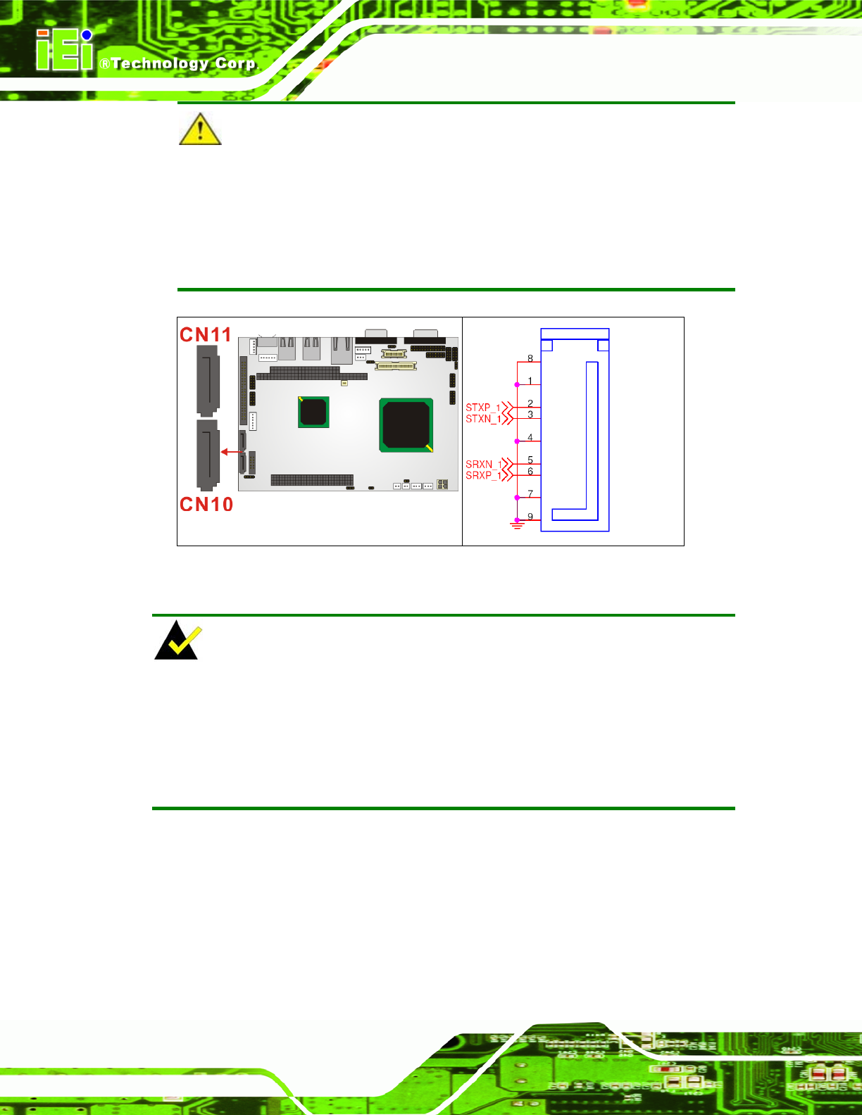
CAUTION!
SATA hard drives may come with both a 4P power connector and a SATA power
interface. Attach either the 4P connector or the SATA power cable to the SATA
hard drives.
DO NOT attach both the power connectors to your SATA hard drives
at the same time! Doing so will cause damage.
Figure 4-23: CN10, CN11 Connector Locations
NOTE:
1. SATA is supported by:
• Windows 2000 SP4
• Windows XP SP1
• Windows 2003, or later versions.
2. Older OSes, such as Windows 98SE or ME, do not support the SATA interface.
4.2.22 Serial Communications Connector
CN Label: CN14, CN15, CN16, CN17, CN19
CN Type: 14-pin headers (2x5 pins)
CN Pinouts: See Table 3-27 and
Table 4-27
CN Location: See Figure 4-24
Page 76