NOVA-945GSE 5.25” SBC NOVA-945GSE 5.25” SBC IEI Technology Corp. MODEL: NOVA-945GSE 5.25” SBC with 1.6 GHz Intel® Atom™ N270 Processor LVDS/VGA/HDTV, Dual PCIe Mini, Dual PCIe GbE, USB 2.0, SATA and RoHS Compliance User Manual Page 1 Rev. 2.
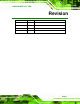
NOVA-945GSE 5.25” SBC Revision Date Version Changes 21 December, 2010 2.01 Modified Table 4 6: LVDS1 Panel Resolution Jumper Settings 19 June, 2009 2.00 Modified based on the NOVA-945GSE-R20 12 March, 2009 1.01 Changed model name 7 November, 2008 1.
NOVA-945GSE 5.25” SBC Copyright COPYRIGHT NOTICE The information in this document is subject to change without prior notice in order to improve reliability, design and function and does not represent a commitment on the part of the manufacturer. In no event will the manufacturer be liable for direct, indirect, special, incidental, or consequential damages arising out of the use or inability to use the product or documentation, even if advised of the possibility of such damages.
NOVA-945GSE 5.25” SBC Table of Contents 1 INTRODUCTION................................................................................................... 13 1.1 INTRODUCTION......................................................................................................... 14 1.2 FEATURES ................................................................................................................. 14 1.3 CONNECTORS ...................................................................................
NOVA-945GSE 5.25” SBC 3.3.9 Fan Connector (+12V, 3-pin) .......................................................................... 40 3.3.10 Front Panel Connector (8-pin) ...................................................................... 41 3.3.11 IDE Connector (44-pin) ................................................................................. 42 3.3.12 Infrared Interface Connector (5-pin) ............................................................. 44 3.3.13 Keyboard/Mouse Connector ...........
NOVA-945GSE 5.25” SBC 4.6.1 Airflow.............................................................................................................. 73 4.6.2 Motherboard Installation................................................................................. 74 4.7 INTERNAL PERIPHERAL DEVICE CONNECTIONS ........................................................ 74 4.7.1 Audio Kit Installation....................................................................................... 74 4.7.
NOVA-945GSE 5.25” SBC 5.7.1 North Bridge Chipset Configuration ............................................................. 121 5.7.1.1 Video Function Configuration ................................................................ 122 5.7.2 SouthBridge Configuration............................................................................ 125 5.8 EXIT ....................................................................................................................... 126 6 SOFTWARE DRIVERS ............
NOVA-945GSE 5.25” SBC List of Figures Figure 1-1: NOVA-945GSE..........................................................................................14 Figure 1-2: NOVA-945GSE Overview [Front View]...................................................15 Figure 1-3: NOVA-945GSE Overview [Solder Side] .................................................16 Figure 1-4: NOVA-945GSE Dimensions (mm) ..........................................................17 Figure 1-5: External Interface Panel Dimensions (mm)......
NOVA-945GSE 5.25” SBC Figure 3-23: TPM Connector Pinout Locations........................................................54 Figure 3-24: TV Connector Pinout Locations...........................................................55 Figure 3-25: USB Connector Pinout Locations........................................................56 Figure 3-26: NOVA-945GSE External Peripheral Interface Connector ..................57 Figure 3-27: RJ-45 Ethernet Connector ..........................................................
NOVA-945GSE 5.25” SBC Figure 6-12: VGA Driver Welcome Screen............................................................. 138 Figure 6-13: VGA Driver License Agreement ........................................................ 139 Figure 6-14: VGA Driver Read Me File.................................................................... 139 Figure 6-15: VGA Driver Setup Operations ........................................................... 140 Figure 6-16: VGA Driver Installation Finish Screen...................
NOVA-945GSE 5.25” SBC List of Tables Table 1-1: Technical Specifications ..........................................................................21 Table 3-1: Peripheral Interface Connectors..............................................................31 Table 3-2: Rear Panel Connectors.............................................................................31 Table 3-3: AT Power Connector Pinouts ..................................................................
NOVA-945GSE 5.25” SBC Table 4-1: Jumpers......................................................................................................66 Table 4-2: AT Power Select Jumper Settings...........................................................66 Table 4-3: CF Card Setup Jumper Settings ..............................................................67 Table 4-4: Clear CMOS Jumper Settings ..................................................................69 Table 4-5: COM 3 Function Select Jumper Settings..
NOVA-945GSE 5.25” SBC List of BIOS Menus Menu 1: Main................................................................................................................85 Menu 2: Advanced.......................................................................................................87 Menu 3: CPU Configuration .......................................................................................87 Menu 4: IDE Configuration ...............................................................................
NOVA-945GSE 5.
NOVA-945GSE 5.25” SBC 1.1 Introduction Figure 1-1: NOVA-945GSE The NOVA-945GSE 5.25” motherboard is embedded 45 nm Intel® Atom™ processor platforms. The Intel® Atom™ processor N270 embedded on the NOVA-945GSE has a 1.60 GHz clock speed, a 533 MHz FSB and a 512 KB L2 cache. The NOVA-945GSE also supports one 200-pin 533 MHz 2.0 GB (max.) DDR2 SDRAM SO-DIMM. The board comes with a LVDS connector that supports 18-bit dual-channel LVDS screens.
NOVA-945GSE 5.25” SBC Dual LVDS support dual display output TPM support 1.3 Connectors The NOVA-945GSE has a wide variety of peripheral interface connectors. Figure 1-2 is a 5 labeled photo of the peripheral interface connectors on the NOVA-945GSE. Figure 1-2: NOVA-945GSE Overview [Front View] Figure 1-3 shows the rear side of the NOVA-945GSE.
NOVA-945GSE 5.25” SBC Figure 1-3: NOVA-945GSE Overview [Solder Side] 1.
NOVA-945GSE 5.25” SBC Figure 1-4: NOVA-945GSE Dimensions (mm) 1.4.1 External Interface Panel Dimensions External peripheral interface connector panel dimensions are shown in Figure 1-5.
NOVA-945GSE 5.25” SBC 1.5 Data Flow Figure 1-6 shows the data flow between the two on-board chipsets and other components 5 installed on the motherboard and described in the following sections of this chapter.
NOVA-945GSE 5.25” SBC 1.6 Technical Specifications NOVA-945GSE technical specifications are listed in the table below. See Chapter 2 for details. Specification NOVA-945GSE Form Factor 5.25” CPU 45 nm 1.6 GHz Intel® Atom™ N270 Front Side Bus (FSB) 533 MHz Northbridge Chipset Intel® 945GSE Southbridge Chipset Intel® ICH7-M Memory One 200-pin SO-DIMM socket supports one 533/400 MHz 2.0 GB (max.
NOVA-945GSE 5.25” SBC Specification NOVA-945GSE Display port One VGA One TV-out connector support HDTV by component interface One 18-bit dual channel LVDS connector One 18/24-bit dual channel LVDS connector (NOVA-945GSELVDS2-N270 only) Ethernet Two RJ-45 GbE ports Keyboard/Mouse One 6-pin header for keyboard and mouse Parallel Port One IEEE 1284 parallel port (26-pin header) supporting normal, EPP and ECP modes Serial Ports Five via internal pin headers Three RS-232 One RS-232/422/485 USB 2.0/1.
NOVA-945GSE 5.25” SBC Specification NOVA-945GSE Environmental and Power Specifications Power Supply ATX and AT power supported Power Consumption 5 V @ 3.49 A 1.
NOVA-945GSE 5.
NOVA-945GSE 5.25” SBC 2.1 Anti-static Precautions WARNING! Failure to take ESD precautions during the installation of the NOVA-945GSE may result in permanent damage to the NOVA-945GSE and severe injury to the user. Electrostatic discharge (ESD) can cause serious damage to electronic components, including the NOVA-945GSE. Dry climates are especially susceptible to ESD.
NOVA-945GSE 5.25” SBC 2.3 Unpacking Checklist NOTE: If any of the components listed in the checklist below are missing, do not proceed with the installation. Contact the IEI reseller or vendor the NOVA-945GSE was purchased from or contact an IEI sales representative directly by sending an email to sales@iei.com.tw. 2 2.3.
NOVA-945GSE 5.25” SBC 1 VGA cable (P/N: 32000-033804-RS) 1 Mini jumper pack (2.0mm) (P/N: 33100-000033-RS) 1 Utility CD 1 Quick Installation Guide 2.3.
NOVA-945GSE 5.25” SBC 802.11 b/g PCIe mini card wireless LAN module with Atheros (P/N: WMPCIE-V01-R10) 802.
NOVA-945GSE 5.
NOVA-945GSE 5.25” SBC 3.1 Peripheral Interface Connectors Section 3.1.1 shows peripheral interface connector locations. Section 3.3 lists all the peripheral interface connectors seen in Section 3.1.1. 3.1.1 NOVA-945GSE Layout Figure 3-1 shows the on-board peripheral connectors, rear panel peripheral connectors 6 and on-board jumpers. Figure 3-1: Connector and Jumper Locations [Front Side] Figure 3-2 shows the solder side of the NOVA-945GSE.
NOVA-945GSE 5.25” SBC Figure 3-2: Connector and Jumper Locations [Solder Side] 3.2 Peripheral Interface Connectors Table 3-1 shows a list of the peripheral interface connectors on the NOVA-945GSE. 6 Detailed descriptions of these connectors can be found below.
NOVA-945GSE 5.
NOVA-945GSE 5.25” SBC TPM connector 20-pin header TPM1 TV Out connector 6-pin header TV1 USB 2.0 connector 8-pin header USB1 USB 2.0 connector 8-pin header USB2 USB 2.0 connector 8-pin header USB3 Table 3-1: Peripheral Interface Connectors 3.2.1 External Interface Panel Connectors Table 3-2 lists the rear panel connectors on the NOVA-945GSE. Detailed descriptions of 6 these connectors can be found in Section 3.4 on page 57.
NOVA-945GSE 5.25” SBC The 4-pin +12V AT power connector is connected directly to an AT power supply. Figure 3-3: AT Power Connector Location PIN NO. DESCRIPTION 1 +5V 2 GND 3 GND 4 +12V Table 3-3: AT Power Connector Pinouts 3.3.2 ATX Power Supply Enable Connector CN Label: J5 CN Type: 3-pin wafer (1x3) CN Location: See Figure 3-4 CN Pinouts: See Table 3-4 The ATX power supply enable connector enables the NOVA-945GSE to be connected to an ATX power supply.
NOVA-945GSE 5.25” SBC Figure 3-4: ATX Power Supply Enable Connector Location PIN NO. DESCRIPTION 1 +5V Standby 2 GND 3 PS-ON Table 3-4: ATX Power Supply Enable Connector Pinouts 3.3.3 Audio Connector (9-pin) CN Label: J8 CN Type: 9-pin header (2x5) CN Location: See Figure 3-5 CN Pinouts: See Table 3-5 The 9-pin audio connector is connected to external audio devices including speakers and microphones for the input and output of audio signals to and from the system.
NOVA-945GSE 5.25” SBC J8 LINEOUTR 1 3 5 7 9 LINEOUTL MICIN 1 3 5 7 9 2 4 6 8 10 2 4 6 8 10 LIR LIL PIN HEADER 2*5 GND_AUD Figure 3-5: Audio Connector Location (9-pin) PIN NO. DESCRIPTION PIN NO. DESCRIPTION 1 LINE_OUTR 2 LIR 3 GND 4 GND 5 LINE_OUTL 6 LIL 7 GND 8 GND 9 MIC_IN 10 N/A Table 3-5: Audio Connector Pinouts (9-pin) 3.3.
NOVA-945GSE 5.25” SBC Figure 3-6: Panel Backlight Connector Pinout Locations PIN NO. DESCRIPTION 1 LCD Backlight Control 2 GROUND 3 +12V 4 GROUND 5 BACKLIGHT Enable Table 3-6: Panel Backlight Connector Pinouts 3.3.
NOVA-945GSE 5.25” SBC INV2_POWER INV2 ENABKL_C 1 2 3 4 5 1 2 3 4 5 CON5/2mm JST_1X5_2MM Figure 3-7: Panel Backlight Connector (2) Pinout Locations PIN NO. DESCRIPTION 1 N/C 2 GROUND 3 +12V 4 GROUND 5 BACKLIGHT Enable Table 3-7: Panel Backlight Connector (2) Pinouts 3.3.
NOVA-945GSE 5.25” SBC Figure 3-8: CF Card Socket Location PIN NO. DESCRIPTION PIN NO.
NOVA-945GSE 5.25” SBC PIN NO. DESCRIPTION PIN NO. DESCRIPTION 16 N/C 41 HDD_RESET 17 N/C 42 IORDY 18 SA2 43 SDREQ 19 SA1 44 SDACK# 20 SA0 45 HDD_ACTIVE# 21 DATA 0 46 66DET 22 DATA 1 47 DATA 8 23 DATA 2 48 DATA 9 24 N/C 49 DATA 10 25 VCC-IN CHECK2 50 GROUND Table 3-8: CF Card Socket Pinouts 3.3.
NOVA-945GSE 5.25” SBC Figure 3-9: VGA Connector Pinout Locations PIN NO. DESCRIPTION PIN NO. DESCRIPTION 1 L_RED 2 DDC_CLK 3 L_GREEN 4 DDC_DATA 5 L_BLUE 6 GND 7 HSYNC 8 GND 9 VSYNC 10 GND Table 3-9: VGA Connector Pinouts 3.3.8 Digital Input/Output (DIO) Connector CN Label: DIO1 CN Type: 10-pin header (2x5) CN Location: See Figure 3-10 CN Pinouts: See Table 3-10 The digital input/output connector is managed through a Super I/O chip. The DIO connector pins are user programmable.
NOVA-945GSE 5.25” SBC Figure 3-10: DIO Connector Connector Locations PIN NO. DESCRIPTION PIN NO. DESCRIPTION 1 GND 2 VCC5 3 Output 3 4 Output 2 5 Output 1 6 Output 0 7 Input 3 8 Input 2 9 Input 1 10 Input 0 Table 3-10: DIO Connector Pinouts 3.3.9 Fan Connector (+12V, 3-pin) CN Label: J1 CN Type: 3-pin wafer (1x3) CN Location: See Figure 3-11 CN Pinouts: See Table 3-11 6 6 The cooling fan connector provides a 12V, 500mA current to the cooling fan.
NOVA-945GSE 5.25” SBC Figure 3-11: +12V Fan Connector Location PIN NO. DESCRIPTION 1 GND 2 +12V 3 Fan Speed Detect Table 3-11: +12V Fan Connector Pinouts 3.3.10 Front Panel Connector (8-pin) CN Label: F_PANEL1 CN Type: 8-pin header (2x4) CN Location: See Figure 3-12 CN Pinouts: See Table 3-12 The front panel connector connects to external switches and indicators to monitor and controls the motherboard.
NOVA-945GSE 5.25” SBC Figure 3-12: Front Panel Connector Pinout Locations (8-pin) FUNCTION PIN DESCRIPTION FUNCTION PIN DESCRIPTION Power 1 PWR_BTN Power LED 2 VCC5 Button 3 GND 4 GND HDD LED 5 HDD_LED+ 6 SYSRST- 7 HDD_LED- 8 GND Reset Table 3-12: Front Panel Connector Pinouts (8-pin) 3.3.
NOVA-945GSE 5.25” SBC Figure 3-13: Secondary IDE Device Connector Locations PIN NO. DESCRIPTION PIN NO.
NOVA-945GSE 5.25” SBC 41 VCC 42 VCC 43 GROUND 44 N/C Table 3-13: Secondary IDE Connector Pinouts 3.3.12 Infrared Interface Connector (5-pin) CN Label: IR1 CN Type: 5-pin header (1x5) CN Location: See Figure 3-14 CN Pinouts: See Table 3-14 6 6 The infrared interface connector supports both Serial Infrared (SIR) and Amplitude Shift Key Infrared (ASKIR) interfaces. Figure 3-14: Infrared Connector Pinout Locations PIN NO.
NOVA-945GSE 5.25” SBC 3.3.13 Keyboard/Mouse Connector CN Label: KB1 CN Type: 6-pin wafer (1x6) CN Location: See Figure 3-15 CN Pinouts: See Table 3-15 The keyboard and mouse connector can be connected to a standard PS/2 cable or PS/2 Y-cable to add keyboard and mouse functionality to the system. Figure 3-15: Keyboard/Mouse Connector Location PIN NO.
NOVA-945GSE 5.25” SBC 3.3.14 LVDS LCD Connector (18-bit) CN Label: LVDS1 CN Type: 30-pin crimp (3x10) CN Location: See Figure 3-16 CN Pinouts: See Table 3-16 6 6 The 30-pin LVDS LCD connector can be connected to single channel or dual channel, 18-bit LVDS panel. Figure 3-16: LVDS LCD Connector Pinout Location PIN NO. DESCRIPTION PIN NO.
NOVA-945GSE 5.25” SBC 9 LVDSACLK+ 10 LVDSACLK- 11 NC 12 NC 13 GND 14 GND 15 LVDSB1+ 16 LVDSB1- 17 LVDSB2+ 18 LVDSB2- 19 LVDSB3+ 20 LVDSB3- 21 LVDSBCLK+ 22 LVDSBCLK- 23 NC 24 NC 25 GND 26 GND 27 LCDVCC 28 LCDVCC 29 LCDVCC 30 LCDVCC Table 3-16: LVDS LCD Port Connector Pinouts 3.3.
NOVA-945GSE 5.25” SBC PIN NO. DESCRIPTION PIN NO. DESCRIPTION 1 GND 2 GND 3 LVDS_A0+ 4 LVDS_A0- 5 LVDS_A1+ 6 LVDS_A1- 7 LVDS_A2+ 8 LVDS_A2- 9 LVDS1_CLK1+ 10 LVDS_CLK1- 11 LVDS_A3+ 12 LVDS_A3- 13 GND 14 GND 15 LVDS_A4+ 16 LVDS_A4- 17 LVDS_A5+ 18 LVDS_A5- 19 LVDS_A6+ 20 LVDS_A6- 21 LVDS1_CLK2+ 22 LVDS1_CLK2- 23 LVDS_A7+ 24 LVDS_A7- 25 GND 26 GND 27 LCDVCC 28 LCDVCC 29 LCDVCC 30 LCDVCC Table 3-17: LVDS LCD Port Connector Pinouts 3.3.
NOVA-945GSE 5.25” SBC Figure 3-18: Parallel Port Connector Location PIN NO. DESCRIPTION PIN NO.
NOVA-945GSE 5.25” SBC 3.3.17 SATA Drive Connectors CN Label: SATA1 (Slave) and SATA2 (Master) CN Type: 7-pin SATA drive connectors CN Location: See Figure 3-19 CN Pinouts: See Table 3-19 6 6 The two SATA drive connectors are each connected to a first generation SATA drive. First generation SATA drives transfer data at speeds as high as 150 Mb/s. The SATA drives can be configured in a RAID configuration. Figure 3-19: SATA Drive Connector Locations PIN NO.
NOVA-945GSE 5.25” SBC 3.3.18 SATA Power Connectors CN Label: CN1 and CN2 CN Type: 2-pin wafer CN Location: See Figure 3-20 CN Pinouts: See Table 3-20 6 6 The SATA power connector provides +5V power to the SATA drive. Figure 3-20: SATA Power Connector Locations PIN NO. DESCRIPTION 1 +5V 2 GND Table 3-20: SATA Power Connector Pinouts 3.3.
NOVA-945GSE 5.25” SBC The 10-pin serial port connector provides a RS-232 serial communications channel. The COM serial port connectors can be connected to external RS-232 serial port devices. Figure 3-21: COM Connector Pinout Locations PIN NO. DESCRIPTION PIN NO. DESCRIPTION 1 DCD 2 DSR 3 RX 4 RTS 5 TX 6 CTS 7 DTR 8 RI 9 GND 10 N/C Table 3-21: COM Connector Pinouts 3.3.
NOVA-945GSE 5.25” SBC JP2 TX_422TX_422+ D+ 1 3 5 RX3RX3+ D- 2 4 6 HEADER_2X3_2 Figure 3-22: COM 3 RS-422/485 Connector Pinout Locations PIN NO. DESCRIPTION PIN NO. DESCRIPTION 1 RS422_TX- 2 RS422_RX- 3 RS422_TX+ 4 RS422_RX+ 5 RS485_DATA+ 6 RS485_DATA- Table 3-22: COM 3 RS-422/485 Connector Pinouts 3.3.
NOVA-945GSE 5.25” SBC Figure 3-23: TPM Connector Pinout Locations PIN NO. DESCRIPTION PIN NO.
NOVA-945GSE 5.25” SBC 3.3.22 TV Out Connector CN Label: TV1 CN Type: 6-pin header (2x3) CN Location: See Figure 3-24 CN Pinouts: See Table 3-24 6 6 The 2x3 pin TV out connector connects to a TV output by using an S-Video or RCA connector. The TV out connector makes displaying media data on a television easier. Figure 3-24: TV Connector Pinout Locations S-Video Connector PIN NO. DESCRIPTION PIN NO.
NOVA-945GSE 5.25” SBC 3.3.23 USB Connectors (Internal) CN Label: USB1, USB2 and USB3 CN Type: 8-pin header (2x4) CN Location: See Figure 3-25 CN Pinouts: See Table 3-25 6 6 The 2x4 USB pin connectors each provide connectivity to two USB 1.1 or two USB 2.0 ports. Each USB connector can support two USB devices. Additional external USB ports are found on the rear panel. The USB ports are used for I/O bus expansion. Figure 3-25: USB Connector Pinout Locations PIN NO. DESCRIPTION PIN NO.
NOVA-945GSE 5.25” SBC 3.4 External Peripheral Interface Connector Panel Figure 3-26 shows the NOVA-945GSE external peripheral interface connector (EPIC) 6 panel. The NOVA-945GSE EPIC panel consists of the following: 2 x RJ-45 LAN connectors Figure 3-26: NOVA-945GSE External Peripheral Interface Connector 3.4.
NOVA-945GSE 5.25” SBC Figure 3-27: RJ-45 Ethernet Connector The RJ-45 Ethernet connector has two status LEDs, one green and one yellow. The green LED indicates activity on the port and the yellow LED indicates the port is linked. See Table 3-27.
NOVA-945GSE 5.
NOVA-945GSE 5.25” SBC 4.1 Anti-static Precautions WARNING: Failure to take ESD precautions during the installation of the NOVA-945GSE may result in permanent damage to the NOVA-945GSE and severe injury to the user. Electrostatic discharge (ESD) can cause serious damage to electronic components, including the NOVA-945GSE. Dry climates are especially susceptible to ESD.
NOVA-945GSE 5.25” SBC 4.2 Installation Considerations NOTE: The following installation notices and installation considerations should be read and understood before the NOVA-945GSE is installed. All installation notices pertaining to the installation of the NOVA-945GSE should be strictly adhered to. Failing to adhere to these precautions may lead to severe damage of the NOVA-945GSE and injury to the person installing the motherboard. 4.2.
NOVA-945GSE 5.25” SBC o When working with the NOVA-945GSE, make sure that it is disconnected from all power supplies and that no electricity is being fed into the system. Before and during the installation of the NOVA-945GSE DO NOT: Remove any of the stickers on the PCB board. These stickers are required for warranty validation. Use the product before verifying all the cables and power connectors are properly connected.
NOVA-945GSE 5.25” SBC 4.3 Unpacking When the NOVA-945GSE is unpacked, please check all the unpacking list items listed in Chapter 3 are indeed present. If any of the unpacking list items are not available please contact the NOVA-945GSE vendor reseller/vendor where the NOVA-945GSE was purchased or contact an IEI sales representative. 4.4 SO-DIMM and CF Card Installation 4.4.1 SO-DIMM Installation WARNING: Using incorrectly specified SO-DIMM may cause permanently damage the NOVA-945GSE.
NOVA-945GSE 5.25” SBC Step 2: Align the SO-DIMM with the socket. The SO-DIMM must be oriented in such a way that the notch in the middle of the SO-DIMM must be aligned with the plastic bridge in the socket. Step 3: Insert the SO-DIMM. Push the SO-DIMM chip into the socket at an angle. (See Figure 4-1) Step 4: Open the SO-DIMM socket arms. Gently pull the arms of the SO-DIMM socket out and push the rear of the SO-DIMM down. (See Figure 4-1) Step 5: Secure the SO-DIMM. Release the arms on the SO-DIMM socket.
NOVA-945GSE 5.25” SBC Figure 4-2: CF Card Installation 4.5 Jumper Settings NOTE: A jumper is a metal bridge used to close an electrical circuit. It consists of two or three metal pins and a small metal clip (often protected by a plastic cover) that slides over the pins to connect them. To CLOSE/SHORT a jumper means connecting the pins of the jumper with the plastic clip and to OPEN a jumper means removing the plastic clip from a jumper.
NOVA-945GSE 5.25” SBC Description Label Type AT Power Mode Setting ATXCTL1 2-pin header CF Card Setting J_CF1 2-pin header Clear CMOS J_CMOS1 3-pin header COM3 Function Select JP1 6-pin header LVDS1 Panel Resolution J_LCD_TYPE1 8-pin header LVDS2 Panel Resolution JP4 8-pin header LVDS1 Voltage Select J_VLVDS1 3-pin header LVDS2 Voltage Select J_VLVDS2 3-pin header Table 4-1: Jumpers 4.5.
NOVA-945GSE 5.25” SBC Figure 4-4: AT Power Select Jumper Location 4.5.2 CF Card Setup Jumper Label: J_CF1 Jumper Type: 2-pin header Jumper Settings: See Table 4-3 Jumper Location: See Figure 4-5 The CF Card Setup jumper sets the CF Type I card or CF Type II cards as either the slave device or the master device. CF Card Setup jumper settings are shown in Table 4-3.
NOVA-945GSE 5.25” SBC Figure 4-5: CF Card Setup Jumper Location 4.5.3 Clear CMOS Jumper Jumper Label: J_CMOS1 Jumper Type: 3-pin header Jumper Settings: See Table 4-4 Jumper Location: See Figure 4-6 6 6 If the NOVA-945GSE fails to boot due to improper BIOS settings, the clear CMOS jumper clears the CMOS data and resets the system BIOS information. To do this, use the jumper cap to close pins 2 and 3 for a few seconds then reinstall the jumper clip back to pins 1 and 2.
NOVA-945GSE 5.25” SBC The clear CMOS jumper settings are shown in Table 4-4. 6 Clear CMOS Description Short 1 - 2 Keep CMOS Setup Short 2 - 3 Clear CMOS Setup Default Table 4-4: Clear CMOS Jumper Settings The location of the clear CMOS jumper is shown in Figure 4-6 below. 6 Figure 4-6: Clear CMOS Jumper 4.5.
NOVA-945GSE 5.25” SBC COM 3 Function Select Description Short 1-2 RS-232 Short 3-4 RS-422 Short 5-6 RS-485 Default Table 4-5: COM 3 Function Select Jumper Settings The COM 3 Function Select jumper location is shown in Figure 4-7. Figure 4-7: COM 3 Function Select Jumper Location 4.5.
NOVA-945GSE 5.
NOVA-945GSE 5.25” SBC 4.5.6 LVDS Voltage Selection Jumpers WARNING: Permanent damage to the screen and NOVA-945GSE may occur if the wrong voltage is selected with this jumper. Please refer to the user guide that cam with the monitor to select the correct voltage. Jumper Label: J_VLVDS1 and J_VLVDS2 Jumper Type: 3-pin header Jumper Settings: See Table 4-8 Jumper Location: See Figure 4-9 The LVDS Voltage Selection jumpers allow the LVDS screen voltages to be set.
NOVA-945GSE 5.25” SBC Figure 4-9: LVDS Voltage Selection Jumper Pinout Locations 4.6 Chassis Installation 4.6.1 Airflow WARNING: Airflow is critical to the cooling of the CPU and other on-board components. The chassis in which the NOVA-945GSE must have air vents to allow cool air to move into the system and hot air to move out. The NOVA-945GSE must be installed in a chassis with ventilation holes on the sides allowing airflow to travel through the heat sink surface.
NOVA-945GSE 5.25” SBC NOTE: IEI has a wide range of backplanes available. Please contact your NOVA-945GSE vendor, reseller or an IEI sales representative at sales@iei.com.tw or visit the IEI website (http://www.ieiworld.com.tw) 2 2 to find out more about the available chassis. 4.6.2 Motherboard Installation To install the NOVA-945GSE motherboard into the chassis please refer to the reference material that came with the chassis. 4.7 Internal Peripheral Device Connections 4.7.
NOVA-945GSE 5.25” SBC Figure 4-10: Audio Kit Cable Connection Step 3: Connect the audio devices. Connect one speaker to the line-in audio jack, one speaker to the line-out audio jack and a microphone to the mic-in audio jack. Step 0: 4.7.2 Keyboard/Mouse Y-cable Connector The NOVA-945GSE is shipped with a keyboard/mouse Y-cable connector.
NOVA-945GSE 5.25” SBC connector to the on-board connectors. See Figure 4-11. Figure 4-11: Keyboard/mouse Y-cable Connection Step 4: Attach PS/2 connectors to the chassis. The keyboard/mouse Y-cable connector is connected to two PS/2 connectors. To secure the PS/2 connectors to the chassis please refer to the installation instructions that came with the chassis. Step 5: Connect the keyboard and mouse.
NOVA-945GSE 5.25” SBC 4.7.3 Single RS-232 Cable (w/o Bracket) The single RS-232 cable consists of one serial port connector attached to a serial communications cable that is then attached to a D-sub 9 male connector. To install the single RS-232 cable, please follow the steps below. Step 1: Locate the connector. The location of the RS-232 connector is shown in Chapter 3. Step 2: Insert the cable connector. Insert the connector into the serial port box header. See Figure 4-12.
NOVA-945GSE 5.25” SBC 4.7.4 SATA Drive Connection The NOVA-945GSE is shipped with two SATA drive cables and one SATA drive power cable. To connect the SATA drives to the connectors, please follow the steps below. Step 1: Locate the connectors. The locations of the SATA drive connectors are shown in Chapter 3. Step 2: Insert the cable connector. Press the clip on the connector at the end of the SATA cable and insert the cable connector into the on-board SATA drive connector. See Figure 4-13.
NOVA-945GSE 5.25” SBC Figure 4-14: SATA Power Drive Connection 4.7.5 USB Cable (Dual Port without Bracket) The NOVA-945GSE is shipped with a dual port USB 2.0 cable. To connect the USB cable connector, please follow the steps below. Step 1: Locate the connectors. The locations of the USB connectors are shown in Chapter 3. WARNING: If the USB pins are not properly aligned, the USB device can burn out. Step 2: Align the connectors. The cable has two connectors.
NOVA-945GSE 5.25” SBC with the USB connectors on the NOVA-945GSE, connect the cable connectors to the on-board connectors. See Figure 4-15. Figure 4-15: Dual USB Cable Connection Step 4: Attach the USB connectors to the chassis. The USB 2.0 connectors each of two retention screw holes. To secure the connectors to the chassis please refer to the installation instructions that came with the chassis.Step 0: 4.
NOVA-945GSE 5.25” SBC 4.8.1 LAN Connection (Single Connector) There are two external RJ-45 LAN connectors. The RJ-45 connectors enable connection to an external network. To connect a LAN cable with an RJ-45 connector, please follow the instructions below. Step 1: Locate the RJ-45 connectors. The locations of the USB connectors are shown in Chapter 4. Step 2: Align the connectors. Align the RJ-45 connector on the LAN cable with one of the RJ-45 connectors on the NOVA-945GSE. See Figure 4-16.
NOVA-945GSE 5.
NOVA-945GSE 5.25” SBC 5.1 Introduction A licensed copy of AMI BIOS is preprogrammed into the ROM BIOS. The BIOS setup program allows users to modify the basic system configuration. This chapter describes how to access the BIOS setup program and the configuration options that may be changed. 5.1.1 Starting Setup The AMI BIOS is activated when the computer is turned on. The setup program can be activated in one of two ways. 1. Press the DELETE key as soon as the system is turned on or 2.
NOVA-945GSE 5.25” SBC F1 key General help, only for Status Page Setup Menu and Option Page Setup Menu F2 /F3 key Change color from total 16 colors. F2 to select color forward. F10 key Save all the CMOS changes, only for Main Menu Table 5-1: BIOS Navigation Keys 5.1.3 Getting Help When F1 is pressed a small help window describing the appropriate keys to use and the possible selections for the highlighted item appears. To exit the Help Window press ESC or the F1 key again. 5.1.
NOVA-945GSE 5.25” SBC 5.2 Main The Main BIOS menu (BIOS Menu 1) appears when the BIOS Setup program is entered. 6 The Main menu gives an overview of the basic system information. BIOS Menu 1: Main System Overview The System Overview lists a brief summary of different system components. The fields in System Overview cannot be changed.
NOVA-945GSE 5.25” SBC o Size: Lists memory size The System Overview field also has two user configurable fields: System Time [xx:xx:xx] Use the System Time option to set the system time. Manually enter the hours, minutes and seconds. System Date [xx/xx/xx] Use the System Date option to set the system date. Manually enter the day, month and year. 5.
NOVA-945GSE 5.25” SBC BIOS Menu 2: Advanced 5.3.1 CPU Configuration Use the CPU Configuration menu (BIOS Menu 3) to view detailed CPU specifications 7 and configure the CPU.
NOVA-945GSE 5.25” SBC The CPU Configuration menu (BIOS Menu 3) lists the following CPU details: Manufacturer: Lists the name of the CPU manufacturer Brand String: Lists the brand name of the CPU being used Frequency: Lists the CPU processing speed FSB Speed: Lists the FSB speed Cache L1: Lists the CPU L1 cache size Cache L2: Lists the CPU L2 cache size 5.3.2 IDE Configuration Use the IDE Configuration menu (BIOS Menu 4) to change and/or set the configuration 7 of the IDE devices installed in the system.
NOVA-945GSE 5.25” SBC Compatible Configures the on-board ATA/IDE controller to be in DEFAULT compatible mode. In this mode, a SATA channel will replace one of the IDE channels. This mode supports up to 4 storage devices. Configures the on-board ATA/IDE controller to be in Enhanced Enhanced mode. In this mode, IDE channels and SATA channels are separated. This mode supports up to 6 storage devices. Some legacy OS do not support this mode.
NOVA-945GSE 5.25” SBC The IDE Configuration menu (BIOS Menu 4) allows changes to the configurations for the 7 IDE devices installed in the system. If an IDE device is detected, and one of the above listed four BIOS configuration options are selected, the IDE configuration options shown in Section 5.3.2.1 appear. 7 5.3.2.1 IDE Master, IDE Slave Use the IDE Master and IDE Slave configuration menu to view both primary and secondary IDE device details and configure the IDE devices connected to the system.
NOVA-945GSE 5.25” SBC Vendor: Lists the device manufacturer Size: List the storage capacity of the device. LBA Mode: Indicates whether the LBA (Logical Block Addressing) is a method of addressing data on a disk drive is supported or not. Block Mode: Block mode boosts IDE drive performance by increasing the amount of data transferred. Only 512 bytes of data can be transferred per interrupt if block mode is not used. Block mode allows transfers of up to 64 KB per interrupt.
NOVA-945GSE 5.25” SBC Device. These include, but are not limited to: ZIP LS-120 LBA/Large Mode [Auto] Use the LBA/Large Mode option to disable or enable BIOS to auto detects LBA (Logical Block Addressing). LBA is a method of addressing data on a disk drive. In LBA mode, the maximum drive capacity is 137 GB. BIOS is prevented from using the LBA mode control on Disabled the specified channel. Auto DEFAULT BIOS auto detects the LBA mode control on the specified channel.
NOVA-945GSE 5.25” SBC PIO Mode [Auto] Use the PIO Mode option to select the IDE PIO (Programmable I/O) mode program timing cycles between the IDE drive and the programmable IDE controller. As the PIO mode increases, the cycle time decreases. Auto DEFAULT BIOS auto detects the PIO mode. Use this value if the IDE disk drive support cannot be determined. 0 PIO mode 0 selected with a maximum transfer rate of 3.3MBps 1 PIO mode 1 selected with a maximum transfer rate of 5.
NOVA-945GSE 5.25” SBC MWDMA0 Multi Word DMA mode 0 selected with a maximum data transfer rate of 4.2MBps MWDMA1 Multi Word DMA mode 1 selected with a maximum data transfer rate of 13.3MBps MWDMA2 Multi Word DMA mode 2 selected with a maximum data transfer rate of 16.6MBps UDMA1 Ultra DMA mode 0 selected with a maximum data transfer rate of 16.6MBps UDMA1 Ultra DMA mode 1 selected with a maximum data transfer rate of 25MBps UDMA2 Ultra DMA mode 2 selected with a maximum data transfer rate of 33.
NOVA-945GSE 5.25” SBC Auto DEFAULT BIOS auto detects HDD SMART support. Disabled Prevents BIOS from using the HDD SMART feature. Enabled Allows BIOS to use the HDD SMART feature 32Bit Data Transfer [Enabled] Use the 32Bit Data Transfer BIOS option to enables or disable 32-bit data transfers. Prevents the BIOS from using 32-bit data transfers. Disabled Enabled DEFAULT Allows BIOS to use 32-bit data transfers on supported hard disk drives. 5.3.
NOVA-945GSE 5.25” SBC Parallel Port Address [378] Use the Parallel Port Address option to select the parallel port base address. No base address is assigned to the Parallel Port Disabled 378 DEFAULT Parallel Port I/O port address is 378 278 Parallel Port I/O port address is 278 3BC Parallel Port I/O port address is 3BC Parallel Port Mode [Normal] Use the Parallel Port Mode option to select the mode the parallel port operates in.
NOVA-945GSE 5.25” SBC Parallel Port IRQ [IRQ7] Use the Parallel Port IRQ selection to set the parallel port interrupt address. IRQ5 is assigned as the parallel port interrupt address IRQ5 IRQ7 DEFAULT IRQ7 is assigned as the parallel port interrupt address Serial Port1 Address [3F8/IRQ4] Use the Serial Port1 Address option to select the Serial Port 1 base address.
NOVA-945GSE 5.25” SBC No base address is assigned to Serial Port 2 Disabled 2F8/IRQ3 Serial Port 2 I/O port address is 3F8 and the interrupt DEFAULT address is IRQ3 Serial Port 2 I/O port address is 3E8 and the interrupt 3E8/IRQ4 address is IRQ4 Serial Port 2 I/O port address is 2E8 and the interrupt 2E8/IRQ3 address is IRQ3 Serial Port2 Mode [Normal] Use the Serial Port2 Mode option to select the Serial Port2 operational mode.
NOVA-945GSE 5.25” SBC Serial port 3 IRQ address is 10 10 11 DEFAULT Serial port 3 IRQ address is 11 Select RS232 or RS485/RS422 [RS/232] Use the Select RS232 or RS485/RS422 option to select the Serial Port 3 signaling mode. DEFAULT RS232 Serial Port 2 signaling mode is RS-232 Serial Port 2 signaling mode is RS-422 or RS-485 RS422/RS485 Serial Port4 Address [2E8] Use the Serial Port4 IRQ option to select the interrupt address for serial port 4.
NOVA-945GSE 5.25” SBC 5.3.4 Hardware Health Configuration The Hardware Health Configuration menu (BIOS Menu 7) shows the operating 7 temperature, fan speeds and system voltages. BIOS Menu 7: Hardware Health Configuration CPU FAN Mode Setting [Full On Mode] Use the CPU FAN Mode Setting option to configure the second fan. Full On Mode Automatic mode DEFAULT Fan is on all the time Fan is off when the temperature is low enough. Parameters must be set by the user.
NOVA-945GSE 5.25” SBC CPU Temp. Limit of OFF CPU Temp. Limit of Start CPU Fan Start PWM Slope PWM 1 When the CPU FAN Mode Setting option is in the PWM Manual Mode, the following parameters can be set. CPU Fan PWM control CPU Temp. Limit of OFF [000] WARNING: Setting this value too high may cause the fan to stop when the CPU is at a high temperature and therefore cause the system to be damaged. The CPU Temp. Limit of OFF option can only be set if the CPU FAN Mode Setting option is set to Automatic Mode.
NOVA-945GSE 5.25” SBC The CPU Temp. Limit of Start option can only be set if the CPU FAN Mode Setting option is set to Automatic Mode. Use the CPU Temp. Limit of Start option to select the CPU temperature at which the cooling fan should automatically turn on. When the fan starts, it rotates using the starting pulse width modulation (PWM) specified in the Fan 3 Start PWM option below. To select a value, select the CPU Temp. Limit of Start option and enter a decimal number between 000 and 127.
NOVA-945GSE 5.25” SBC 4 PWM 8 PWM 15 PWM The following system parameters and values are shown. The system parameters that are monitored are: System Temperatures: The following system temperatures are monitored o o CPU Temperature System Temperature Fan Speeds: The CPU cooling fan speed is monitored. o CPU Fan Speed Voltages: The following system voltages are monitored o o o o o o o o o CPU Core +1.05V +3.30V +5.00V +12.0 V +1.5V +1.8V 5VSB VBAT 5.3.
NOVA-945GSE 5.25” SBC BIOS Menu 8: Power Configuration Select AT/ATX Power [ATX Power] Use the Select AT/ATX Power BIOS option to select the power mode for the system. Use AT power mode AT Power ATX Power BY HARDWARE Page 104 DEFAULT Use ATX power mode The power mode is selected by the on-board jumper.
NOVA-945GSE 5.25” SBC 5.3.6 APM Configuration The APM Configuration menu (BIOS Menu 9) allows the advanced power management options to be configured. BIOS Menu 9:Advanced Power Management Configuration Restore on AC Power Loss [Last State] Use the Restore on AC Power Loss BIOS option to specify what state the system returns to if there is a sudden loss of power to the system.
NOVA-945GSE 5.25” SBC Power Button Mode [On/Off] Use the Power Button Mode BIOS to specify how the power button functions. On/Off DEFAULT When the power button is pressed the system is either turned on or off When the power button is pressed the system goes into Suspend suspend mode Resume on Keyboard/Mouse [Disabled] Use the Resume on Keyboard/Mouse BIOS option to enable activity on either the keyboard or mouse to rouse the system from a suspend or standby state.
NOVA-945GSE 5.25” SBC Wake event generated by an incoming call Enabled Resume on PCI-Express WAKE# [Disabled] Use the Resume PCI-Express WAKE# BIOS option to enable activity on the PCI-Express WAKE# signal to rouse the system from a suspend or standby state.
NOVA-945GSE 5.25” SBC allows a remote host running a terminal program to display and configure the BIOS settings. BIOS Menu 10: Remote Access Configuration [Advanced] Remote Access [Disabled] Use the Remote Access option to enable or disable access to the remote functionalities of the system. Disabled Enabled DEFAULT Remote access is disabled.
NOVA-945GSE 5.25” SBC These configuration options are discussed below. Serial Port Number [COM1] Use the Serial Port Number option allows to select the serial port used for remote access. COM1 DEFAULT System is remotely accessed through COM1 COM2 System is remotely accessed through COM2 COM3 System is remotely accessed through COM3 COM4 System is remotely accessed through COM4 NOTE: Make sure the selected COM port is enabled through the Super I/O configuration menu.
NOVA-945GSE 5.25” SBC NOTE: Identical baud rate setting musts be set on the host (a management computer running a terminal software) and the slave Redirection After BIOS POST [Always] Use the Redirection After BIOS POST option to specify when console redirection should occur.
NOVA-945GSE 5.25” SBC 5.3.8 USB Configuration Use the USB Configuration menu (BIOS Menu 11) to read USB configuration 7 information and configure the USB settings. BIOS Menu 11: USB Configuration USB Functions [Enabled] Use the USB Function option to enable or disable the USB controllers. USB controllers are enabled Disabled Enabled DEFAULT USB controllers are disabled USB 2.0 Controller [Enabled] The USB 2.0 Controller BIOS option enables or disables the USB 2.
NOVA-945GSE 5.25” SBC Legacy USB Support [Enabled] Use the Legacy USB Support BIOS option to enable USB mouse and USB keyboard support. Normally if this option is not enabled, any attached USB mouse or USB keyboard does not become available until a USB compatible operating system is fully booted with all USB drivers loaded. When this option is enabled, any attached USB mouse or USB keyboard can control the system even when there is no USB driver loaded onto the system.
NOVA-945GSE 5.25” SBC 5.3.9 Trusted Computing Use the Trusted Computing menu (BIOS Menu 12) to configure settings related to the Trusted Computing Group (TCG) Trusted Platform Module (TPM). BIOS Menu 12: Trusted Computing TCG/TPM Support [No] Use the TCG/TPM Support option to configure support for the TPM. No Yes DEFAULT TPM support is disabled. TPM support is enabled.
NOVA-945GSE 5.25” SBC 5.4 PCI/PnP Use the PCI/PnP menu (BIOS Menu 13) to configure advanced PCI and PnP settings. 7 WARNING: Setting wrong values for the BIOS selections in the PCIPnP BIOS menu may cause the system to malfunction. BIOS Menu 13: PCI/PnP Configuration IRQ# [Available] Use the IRQ# address to specify what IRQs can be assigned to a particular peripheral device.
NOVA-945GSE 5.25” SBC The specified IRQ is reserved for use by Legacy ISA Reserved devices Available IRQ addresses are: IRQ3 IRQ4 IRQ5 IRQ7 IRQ9 IRQ10 IRQ 11 IRQ 14 IRQ 15 DMA Channel# [Available] Use the DMA Channel# option to assign a specific DMA channel to a particular PCI/PnP device.
NOVA-945GSE 5.25” SBC 5.5 Boot Use the Boot menu (BIOS Menu 14) to configure system boot options. 7 BIOS Menu 14: Boot 5.5.1 Boot Settings Configuration Use the Boot Settings Configuration menu (BIOS Menu 15) to configure advanced system boot options.
NOVA-945GSE 5.25” SBC BIOS Menu 15: Boot Settings Configuration Quick Boot [Enabled] Use the Quick Boot BIOS option to make the computer speed up the boot process. No POST procedures are skipped Disabled Enabled DEFAULT Some POST procedures are skipped to decrease the system boot time Quiet Boot [Enabled] Use the Quiet Boot BIOS option to select the screen display when the system boots.
NOVA-945GSE 5.25” SBC AddOn ROM Display Mode [Force BIOS] The AddOn ROM Display Mode option allows add-on ROM (read-only memory) messages to be displayed. Force BIOS DEFAULT Allows the computer system to force a third party BIOS to display during system boot. Allows the computer system to display the Keep Current information during system boot. Bootup Num-Lock [On] The Bootup Num-Lock BIOS option allows the Number Lock setting to be modified during boot up.
NOVA-945GSE 5.25” SBC Disabled DEFAULT Cannot be booted from a remote system through the LAN Enabled DEFAULT Can be booted from a remote system through the LAN 5.6 Security Use the Security menu (BIOS Menu 16) to set system and user passwords. 7 BIOS Menu 16: Security Change Supervisor Password Use the Change Supervisor Password to set or change a supervisor password. The default for this option is Not Installed. If a supervisor password must be installed, select this field and enter the password.
NOVA-945GSE 5.25” SBC Change User Password Use the Change User Password to set or change a user password. The default for this option is Not Installed. If a user password must be installed, select this field and enter the password. After the password has been added, Install appears next to Change User Password. 5.
NOVA-945GSE 5.25” SBC 5.7.1 North Bridge Chipset Configuration Use the North Bridge Chipset Configuration menu (BIOS Menu 18) to configure the 7 Northbridge chipset settings. BIOS Menu 18:North Bridge Chipset Configuration Memory Hole [Disabled] The Memory Hole reserves the memory space between 15MB and 16MB for ISA expansion cards that require a specified area of memory to work properly.
NOVA-945GSE 5.25” SBC Internal Graphics Mode Select [Enable, 8MB] The Internal Graphic Mode Select option determines the amount of system memory that can be used by the Internal graphics device. Disable 1MB of memory used by internal graphics device Enable, 1MB Enable, 8MB DEFAULT 8MB of memory used by internal graphics device Boots Graphics Adapter Priority [PCI/IGD] Use the Boots Graphics Adapter option to select the graphics controller used as the primary boot device.
NOVA-945GSE 5.25” SBC Main Advanced PCIPNP BIOS SETUP UTILITY Boot Security Chipset Power Exit Video Function Configuration ⎯⎯⎯⎯⎯⎯⎯⎯⎯⎯⎯⎯⎯⎯⎯⎯⎯⎯⎯⎯⎯⎯⎯⎯⎯⎯⎯⎯⎯⎯⎯ DVMT Mode Select [DVMT Mode] DVMT/Fixed Memory [128 MB] Boot Display Device LVDS2 Panel Type LVDS2 Current Jumper Setting [CRT] [1024x768 24b] [1024x768 18b] ↑ ↓ Enter F1 F10 ESC Select Screen Select Item Go to SubScreen General Help Save and Exit Exit v02.61 ©Copyright 1985-2006, American Megatrends, Inc.
NOVA-945GSE 5.25” SBC selected, the maximum amount of graphics memory is 128MB. Configuration options are listed below. 64MB 128MB DEFAULT Maximum DVMT Boot Display Device [CRT] Use the Boot Display Device option to select the display device used by the system when it boots. Configuration options are listed below. Auto CRT DEFAULT TV LVDS LVDS1 LVDS2 Panel Type [1024x768 24b] Use the LVDS2 Panel Type option to select the type of flat panel connected to LVDS2 connector on the system.
NOVA-945GSE 5.25” SBC 5.7.2 SouthBridge Configuration The SouthBridge Configuration menu (BIOS Menu 20) the southbridge chipset to be 7 configured. BIOS Menu 20:SouthBridge Chipset Configuration Audio Controller [Auto] The Audio Controller option enables or disables the audio controller. The onboard audio controller is automatically Auto detected and enabled All Disabled DEFAULT The on-board audio controller is disabled. Spread Spectrum [Disabled] Use the Spread Spectrum option to reduce the EMI.
NOVA-945GSE 5.25” SBC EMI. This benefit may in some cases be outweighed by problems with timing-critical devices, such as a clock-sensitive SCSI device. Disabled DEFAULT EMI not reduced EMI reduced Enabled 5.8 Exit Use the Exit menu (BIOS Menu 21) to load default BIOS values, optimal failsafe values 7 and to save configuration changes.
NOVA-945GSE 5.25” SBC Discard Changes and Exit Use the Discard Changes and Exit option to exit the BIOS configuration setup program without saving the changes made to the system. Discard Changes Use the Discard Changes option to discard the changes and remain in the BIOS configuration setup program. Load Optimal Defaults Use the Load Optimal Defaults option to load the optimal default values for each of the parameters on the Setup menus. F9 key can be used for this operation.
NOVA-945GSE 5.
NOVA-945GSE 5.25” SBC 6.1 Available Software Drivers NOTE: The content of the CD may vary throughout the life cycle of the product and is subject to change without prior notice. Visit the IEI website or contact technical support for the latest updates. The following drivers can be installed on the system: Chipset VGA LAN Audio Installation instructions are given below. 6.2 Starting the Driver Program To access the driver installation programs, please do the following.
NOVA-945GSE 5.25” SBC Figure 6-1: Start Up Screen Step 3: Click NOVA-945GSE. Step 4: The screen in appears. Figure 6-2: Select Operating System Step 5: Select the operating system installed on the NOVA-945GSE system.
NOVA-945GSE 5.25” SBC manual describes the installation for a Windows XP operating system. Step 6: The list of drivers in Figure 6-3 appears. Figure 6-3: Drivers 6.3 Chipset Driver Installation To install the chipset driver, please do the following. Step 1: Access the driver list shown in Figure 6-3. (See Section 6.2) Step 2: Click “1-Chipset Driver” Step 3: The setup files are extracted as shown in Figure 6-4.
NOVA-945GSE 5.25” SBC Figure 6-4: Chipset Driver Screen Step 4: When the setup files are completely extracted the Welcome Screen in Figure 6-5 appears. Figure 6-5: Chipset Driver Welcome Screen Step 5: Click Next to continue.
NOVA-945GSE 5.25” SBC Step 6: The license agreement in Figure 6-6 appears. Step 7: Read the License Agreement. Step 8: Click the Yes icon to continue. Figure 6-6: Chipset Driver License Agreement Step 9: The Read Me file in Figure 6-7 appears. Step 10: Click Next to continue.
NOVA-945GSE 5.25” SBC Figure 6-7: Chipset Driver Read Me File Step 11: Setup Operations are performed as shown in Figure 6-8.
NOVA-945GSE 5.25” SBC Figure 6-8: Chipset Driver Setup Operations Step 12: Once the Setup Operations are complete, click the Next icon to continue. Step 13: The Finish screen appears. Step 14: Select “Yes, I want to restart the computer now” and click the Finish icon. See Figure 6-9.
NOVA-945GSE 5.25” SBC Figure 6-9: Chipset Driver Installation Finish Screen 6.4 VGA Driver Installation To install the VGA driver, please do the following. Step 1: Access the driver list shown in Figure 6-3. (See Section 6.2) Step 2: Click “2-VGA” Step 3: The VGA Read Me file in Figure 6-10 appears. Step 4: Click Next to continue.
NOVA-945GSE 5.25” SBC Figure 6-10: VGA Driver Read Me File Step 5: The installation files are extracted. See Figure 6-11. Figure 6-11: VGA Driver Setup Files Extracted Step 6: The Welcome Screen in Figure 6-12 appears.
NOVA-945GSE 5.25” SBC Figure 6-12: VGA Driver Welcome Screen Step 7: Click Next to continue. Step 8: The license agreement in Figure 6-13 appears. Step 9: Read the License Agreement. Step 10: Click the Yes icon to continue.
NOVA-945GSE 5.25” SBC Figure 6-13: VGA Driver License Agreement Step 11: The Read Me file in Figure 6-14 appears. Step 12: Click Next to continue. Figure 6-14: VGA Driver Read Me File Step 13: Setup Operations are performed as shown in Figure 6-15.
NOVA-945GSE 5.25” SBC Figure 6-15: VGA Driver Setup Operations Step 14: Once the Setup Operations are complete, click the Next icon to continue. Step 15: The Finish screen appears. Step 16: Select “Yes, I want to restart the computer now” and click the Finish icon. See Figure 6-16.
NOVA-945GSE 5.25” SBC 6.5 LAN Driver Installation To install the chipset driver, please do the following. Step 1: Access the driver list shown in Figure 6-3. (See Section 6.2) Step 2: Click “3-LAN” Step 3: The Welcome screen in Figure 6-17 appears. Figure 6-17: LAN Driver Welcome Screen Step 4: Click Next to continue. Step 5: The Ready to Install screen in Figure 6-18 appears. Step 6: Click Next to proceed with the installation.
NOVA-945GSE 5.25” SBC Figure 6-18: LAN Driver Welcome Screen Step 7: The program begins to install. Step 8: The installation progress can be monitored in the progress bar shown in Figure 6-19.
NOVA-945GSE 5.25” SBC Step 9: When the driver installation is complete, the screen in Figure 6-20 appears. Figure 6-20: LAN Driver Installation Complete 6.6 Audio Driver Installation To install the chipset driver, please do the following. Step 1: Access the driver list shown in Figure 6-3. (See Section 6.2) Step 2: Click “4-Audio” Step 3: The screen in Figure 6-21 appears.
NOVA-945GSE 5.25” SBC Figure 6-21: Audio Driver Options Step 4: Select “ALC655” in Figure 6-21 Step 5: Locate the following directory: x:\4-Audio\ALC655\Windows\Windows 98Gold, 98se, Me, 2000, XP, 2003(32,64 bits)\A3.84. Click the WDM_A384.exe icon. Step 6: The AC’97 Driver Installation screen in Figure 6-22 appears. Step 7: Click Next to continue.
NOVA-945GSE 5.25” SBC Figure 6-22: AC’97 Driver Installation Welcome Screen Step 8: The Verification window in Figure 6-23 may appear. Step 9: Click “Continue Anyway.” Figure 6-23: AC’97 Driver Installation Verification Step 10: The driver installation begins. See Figure 6-24.
NOVA-945GSE 5.25” SBC Figure 6-24: AC’97 Driver Installation Step 11: When the driver is installed, the driver installation finish screen in Figure 6-25 appears. Step 12: Select “Yes, I wish to restart my computer now” And click Finish Figure 6-25: AC’97 Driver Installation Complete Step 13: The system reboots.
NOVA-945GSE 5.
NOVA-945GSE 5.25” SBC System Overview............................................................................................85 System Time [xx:xx:xx] .................................................................................86 System Date [xx/xx/xx] ..................................................................................86 ATA/IDE Configurations [Compatible] .........................................................88 Legacy IDE Channels [SATA Pri, PATA Sec] ...........................
NOVA-945GSE 5.25” SBC CPU Temp. Limit of Start [020] .................................................................. 101 CPU Fan Start PWM [070]........................................................................... 102 Slope PWM [0.5 PWM].............................................................................. 102 Select AT/ATX Power [ATX Power] ........................................................... 104 Restore on AC Power Loss [Last State] .................................................
NOVA-945GSE 5.25” SBC AddOn ROM Display Mode [Force BIOS] ................................................. 118 Bootup Num-Lock [On]............................................................................... 118 Boot From LAN Support [Disabled] .......................................................... 118 Change Supervisor Password ................................................................... 119 Change User Password ..............................................................................
NOVA-945GSE 5.
NOVA-945GSE 5.25” SBC AC ’97 Audio Codec 97 (AC’97) refers to a codec standard developed by Intel® in 1997. ACPI Advanced Configuration and Power Interface (ACPI) is an OS-directed configuration, power management, and thermal management interface. AHCI Advanced Host Controller Interface (AHCI) is a SATA Host controller register-level interface. ATA The Advanced Technology Attachment (ATA) interface connects storage devices including hard disks and CD-ROM drives to a computer.
NOVA-945GSE 5.25” SBC computer is usually a male DE-9 connector. DAC The Digital-to-Analog Converter (DAC) converts digital signals to analog signals. DDR Double Data Rate refers to a data bus transferring data on both the rising and falling edges of the clock signal. DMA Direct Memory Access (DMA) enables some peripheral devices to bypass the system processor and communicate directly with the system memory.
NOVA-945GSE 5.25” SBC MAC The Media Access Control (MAC) protocol enables several terminals or network nodes to communicate in a LAN, or other multipoint networks. PCIe PCI Express (PCIe) is a communications bus that uses dual data lines for full-duplex (two-way) serial (point-to-point) communications between the SBC components and/or expansion cards and the SBC chipsets. Each line has a 2.5 Gbps data transmission rate and a 250 MBps sustained data transfer rate.
NOVA-945GSE 5.25” SBC asynchronous communications on the system and manages the system’s serial communication (COM) ports. UHCI The Universal Host Controller Interface (UHCI) specification is a register-level interface description for USB 1.1 Host Controllers. USB The Universal Serial Bus (USB) is an external bus standard for interfacing devices. USB 1.1 supports 12Mbps data transfer rates, while USB 2.0 supports 480Mbps data transfer rates.
NOVA-945GSE 5.
NOVA-945GSE 5.25” SBC C.1 DIO Interface Introduction The DIO connector on the NOVA-945GSE is interfaced to GPIO ports on the ITE IT8718F Super I/O chipset. The DIO has both 4-bit digital inputs and 4-bit digital outputs. The digital inputs and digital outputs are generally control signals that control the on/off circuit of external devices or TTL devices. Data can be read or written to the selected address to enable the DIO functions.
NOVA-945GSE 5.25” SBC C.3 Assembly Language Samples C.3.1 Enable the DIO Input Function The BIOS interrupt call INT 15H controls the digital I/O. An assembly program to enable digital I/O input functions is listed below. MOV AX, 6F08H Sets the digital port as input INT 15H Initiates the INT 15H BIOS call C.3.2 Enable the DIO Output Function The BIOS interrupt call INT 15H controls the digital I/O. An assembly program to enable digital I/O output functions is listed below.
NOVA-945GSE 5.
NOVA-945GSE 5.25” SBC NOTE: The following discussion applies to DOS environment. IEI support is contacted or the IEI website visited for specific drivers for more sophisticated operating systems, e.g., Windows and Linux. The Watchdog Timer is provided to ensure that standalone systems can always recover from catastrophic conditions that cause the CPU to crash. This condition may have occurred by external EMI or a software bug.
NOVA-945GSE 5.25” SBC NOTE: When exiting a program it is necessary to disable the Watchdog Timer, otherwise the system resets.
NOVA-945GSE 5.
NOVA-945GSE 5.25” SBC E.
NOVA-945GSE 5.
NOVA-945GSE 5.25” SBC E.
NOVA-945GSE 5.25” SBC E.
NOVA-945GSE 5.
NOVA-945GSE 5.25” SBC F.1 Hazardous Material Disclosure Table for IPB Products Certified as RoHS Compliant Under 2002/95/EC Without Mercury The details provided in this appendix are to ensure that the product is compliant with the Peoples Republic of China (China) RoHS standards. The table below acknowledges the presences of small quantities of certain materials in the product, and is applicable to China RoHS only.
NOVA-945GSE 5.
NOVA-945GSE 5.