
Manual


PCISA -9652 Half-Size CPU Card
Page 83
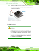
close automatically and secure the DIMM to the socket. See Figure 5-6.
Step 4: Removing a DIMM. To remove a DIMM, push both handles outward. The
memory module is ejected by a mechanism in the socket.Step 0:
5.4 Jumper Settings
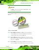
NOTE:
A jumper is a metal bridge used to close an
electrical circuit. It consists of two or three metal
pins and a small metal clip (often protected by a
plastic cover) that slides over the pins to connect
them. To CLOSE/SHORT a jumper means
connecting the pins of the jumper with the plastic
clip and to OPEN a jumper means removing the
plastic clip from a jumper.
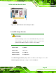
Figure 5-7: Jumper Locations
Before the PCISA-9652 is installed in the system, the jumpers must be set in accordance
with the desired configuration. The jumpers on the PCISA-9652 are listed in
Table 5-1.
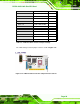
Description Label Type
CF card setup JCF1 2-pin header
Clear CMOS J_CMOS1 3-pin header
COM 2 function selection JP2 6-pn header
LVDS LCD voltage selection J_LVDS1 3-pin header
LVDS LCD resolution selection J_LCD_TYPE1 8-pin header
Table 5-1: Jumpers