
Manual


PCISA -9652 Half-Size CPU Card
Page 53
7 NC 8 NC
Table 4-10: Flash SPI ROM Connector Pinouts
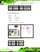
4.2.9 Front Panel Connector
CN Label: F_PANEL1
CN Type:
8-pin header (2x4)
CN Location: See
Figure 4-11
CN Pinouts: See
Table 4-11
The front panel connector connects to several external switches and indicators to monitor
and control the motherboard. These indicators and switches include:
Power LED
Power button
Reset button
HDD LED
Figure 4-11: Front Panel Connector Location