
Manual


PCISA-9652 Half-Size CPU Card
Page 54
FUNCTION PIN DESCRIPTION FUNCTION PIN DESCRIPTION
1 PWR_BTN+ 2 PWR_LED+ Power
Button
3 PWR_BTN-
Power
LED
4 PWR_LED-
5 HDD_LED+ 6 RESET+ HDD LED
7 HDD_LED-
Reset
8 RESET-
Table 4-11: Front Panel Connector Pinouts
4.2.10 IDE Connector
CN Label: PIDE1
CN Type:
40-pin box header (2x20)
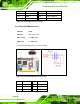
CN Location: See
Figure 4-12
CN Pinouts: See
Table 4-12
One primary 40-pin IDE device connector on the PCISA-9652 motherboard supports
connectivity to ATA 100/66/33 IDE devices with data transfer rates up to 100MB/s.