
Manual


PCISA -9652 Half-Size CPU Card
Page 67
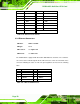
Figure 4-22: TV Connector Pinout Locations
S-Video Connector
PIN NO. DESCRIPTION PIN NO. DESCRIPTION
1 GND 2 AGREEN_Y
3 GND 4 ARED_C
RCA Connector (only video signal)
5 GND 6 ABLUE_CVBS
Table 4-22: TV Port Connector Pinouts
4.2.21 Internal USB Connectors
CN Label: USB01 and USB23
CN Type:
8-pin header (2x4)
CN Location: See
Figure 4-23
CN Pinouts: See
Table 4-23
One 2x4 pin connector provides connectivity to two USB 2.0 ports. The USB ports are
used for I/O bus expansion.