
Manual


PCISA-9652 Half-Size CPU Card
Page 70
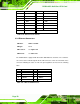
PIN NO. DESCRIPTION PIN NO. DESCRIPTION
1 RED 2 GREEN
3 BLUE 4 N/C
5 GND 6 GND
7 GND 8 GND
9 VCC 10 GND
11 N/C 12 DDC DAT
13 HSYNC 14 VSYNC
15 DDC CLK
Table 4-24: VGA Connector Pinouts
4.3.2 Ethernet Connectors
CN Label: LAN1 and LAN2
CN Type:
RJ-45
CN Location: See
Figure 4-24
CN Pinouts: See
Table 4-25
The PCISA-9652 is equipped with two built-in GbE Ethernet controllers. The controllers
can connect to the LAN through two RJ-45 LAN connectors. There are two LEDs on the
connector indicating the status of LAN. The pin assignments are listed in the following
table:
PIN DESCRIPTION PIN DESCRIPTION
1 MDIA3- 5 MDIA1+
2 MDIA3+ 6 MDIA2+-
3 MDIA2- 7 MDIA0-
4 MDIA1- 8 MDIA0+
Table 4-25: LAN1 and LAN2 Pinouts