
Instruction Manual


PICOe-PV-D4251/N4551/D5251 User Manual
Page 15
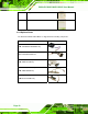
3.1.2 Peripheral Interface Connectors
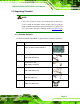
769HTable 3-1 shows a list of the peripheral interface connectors on the
PICOe-PV-D4251/N4551/D5251. Detailed descriptions of these connectors can be found
below.
Connector Type Label
Audio connector 9-pin header J_AUDIO1
ATX power control connector 3-pin wafer ATXCTL1
Backlight inverter connector 5-pin wafer INV1
Battery connector 2-pin wafer BAT1
CompactFlash® socket 50-pin CF socket CF1
CPU Fan connector 4-pin wafer CPU_FAN1
Digital input/output (DIO) connector 10-pin header DIO1
Front panel connector 8-pin header F_PANEL1
LPC connector 20-pin CN1
Infrared interface (IrDA) connector 5-pin header IR1
Keyboard connector 6-pin wafer KB/MS1
LVDS LCD connector 20-pin crimp LVDS1
Parallel port connector 26-pin header LPT1
Serial ATA (SATA) drive connectors 7-pin SATA SATA1, SATA2, SATA3
Serial port connectors (RS-232) 10-pin header COM1, COM2, COM4
Serial port connectors
(RS-232/422-485)
14-pin header COM3
SMBus connector 4-pin wafer CN1
USB 2.0 connectors 8-pin header USB0_1, USB2_3,
USB4_5
Table 3-1: Peripheral Interface Connectors
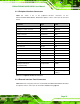
3.1.3 External Interface Panel Connectors
770HTable 3-2 lists the rear panel connectors on the PICOe-PV-D4251/N4551/D5251. Detailed
descriptions of these connectors can be found in Section
771H3.3 on page 772H32.