
Instruction Manual

PICOe-PV-D4251/N4551/D5251 User Manual
Page 22
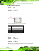
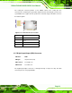
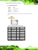
Figure 3-9: DIO Connector Locations
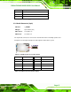
Pin Description Pin Description
1 GND 2 +5V
3 Output 3 4 Output 2
5 Output 1 6 Output 0
7 Input 3 8 Input 2
9 Input 1 10 Input 0
Table 3-9: DIO Connector Connector Pinouts
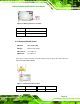
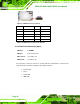
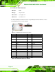
3.2.8 Front Panel Connector (8-pin)
CN Label: F_PANEL1
CN Type:
8-pin header (2x4)
CN Location:
See Figure 3-10
CN Pinouts:
See Table 3-10
The front panel connector connects to external switches and indicators to monitor and
controls the CPU card. These indicators and switches include:
Power button
Reset
Power LED
HDD LED