
Instruction Manual

PICOe-PV-D4251/N4551/D5251 User Manual
Page 23
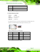
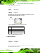
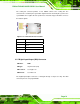
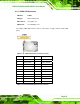
Figure 3-10: Front Panel Connector Pinout Locations (8-pin)
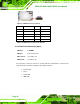
FUNCTION PIN DESCRIPTION FUNCTION PIN DESCRIPTION
1 PWR_BTN+ 2 PWR_LED+ Power Button
3 PWR_BTN-
Power LED
4 PWR_LED-
5 HDD_LED+ 6 RESET+ HDD LED
7 HDD_LED-
Reset
8 RESET-
Table 3-10: Front Panel Connector Pinouts (8-pin)
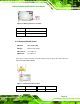
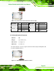
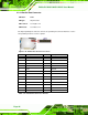
3.2.9 Infrared Interface Connector
CN Label: IR1
CN Type:
5-pin header (1x5)
CN Location:
See
787HFigure 3-11
CN Pinouts:
See
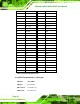
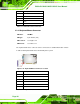
788HTable 3-11
The infrared interface connector supports both Serial Infrared (SIR) and Amplitude Shift
Key Infrared (ASKIR) interfaces.
Figure 3-11: Infrared Connector Pinout Locations