
Instruction Manual

PICOe-PV-D4251/N4551/D5251 User Manual
Page 31
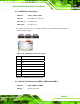
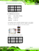
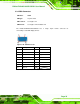
Pin Description Pin Description
1 SPI_VCC 2 GND
3 SPI_CS 4 SPI_CLK
5 SPI_SO 6 SPI_SI
7 NC 8 NC
Table 3-19: SPI Flash Connector
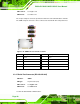
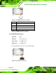
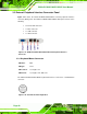
3.2.18 USB Connectors (Internal)
CN Label: USB0_1, USB2_3 and USB4_5
CN Type:
8-pin header (2x4)
CN Location:
See
801HFigure 3-20
CN Pinouts:
See
802HTable 3-20
The 2x4 USB pin connectors each provide connectivity to two USB 1.1 or two USB 2.0
ports. Each USB connector can support two USB devices. Additional external USB ports
are found on the rear panel. The USB ports are used for I/O bus expansion.
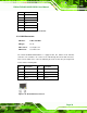
Figure 3-20: USB Connector Pinout Locations
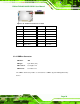
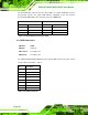
Pin Description Pin Description
1 VCC 2 GND
3 DATA- 4 DATA+
5 DATA+ 6 DATA-
7 GND 8 VCC
Table 3-20: USB Port Connector Pinouts