
Instruction Manual


PICOe-PV-D4251/N4551/D5251 User Manual
Page 58
the PICOe-PV-D4251/N4551/D5251 LPT box-header connector. See Figure
4-15.
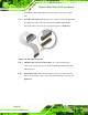
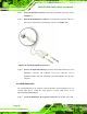
Step 3: Insert the cable connectors. Once the cable connector is properly aligned with
the 26-pin box-header connector on the PICOe-PV-D4251/N4551/D5251,
connect the cable connector to the on-board connector. See Figure 4-15.
Figure 4-15: LPT Cable Connection
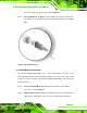
Step 4: Attach the LPT connector to the chassis. To secure the LPT interface
connector to the chassis please refer to the installation instructions that came
with the chassis.
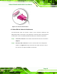
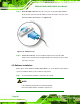
Step 5: Connect LPT device. Once the LPT interface connector is connected to the
chassis, the LPT device can be connected to the LPT interface connector. See
Figure 4-16