
User guide


PICOe-PV-D4251/N4551/D5251 User Manual
Page 15
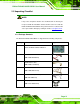
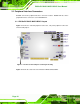
Figure 3-2: Connector and Jumper Locations [Solder Side]
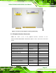
3.1.2 Peripheral Interface Connectors
6Table 3-1 shows a list of the peripheral interface connectors on the
PICOe-PV-D4251/N4551/D5251. Detailed descriptions of these connectors can be found
below.
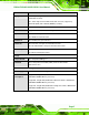
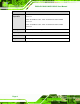
Connector Type Label
Audio connector 9-pin header J_AUDIO1
ATX power control connector 3-pin wafer ATXCTL1
Backlight inverter connector 5-pin wafer INV1
Battery connector 2-pin wafer BAT1
CompactFlash® socket 50-pin CF socket CF1
CPU Fan connector 4-pin wafer CPU_FAN1
Digital input/output (DIO) connector 10-pin header DIO1
Front panel connector 8-pin header F_PANEL1
Infrared interface (IrDA) connector 5-pin header IR1
Keyboard/Mouse connector 6-pin wafer KB/MS1
LVDS LCD connector 20-pin crimp LVDS1
Parallel port connector 26-pin box header LPT1