
User guide


PICOe-PV-D4251/N4551/D5251 User Manual
Page 16
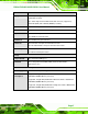
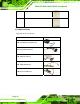
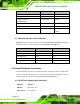
Connector Type Label
Serial ATA (SATA) drive connectors 7-pin SATA SATA1, SATA2, SATA3
Serial port connectors (RS-232) 10-pin header COM1, COM2, COM4
Serial port connectors
(RS-232/422-485)
14-pin header COM3
SMBus connector 4-pin wafer CN1
SPI flash connector 8-pin header SPI1
USB 2.0 connectors 8-pin header USB0_1, USB2_3,
USB4_5
Table 3-1: Peripheral Interface Connectors
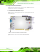
3.1.3 External Interface Panel Connectors
6Table 3-2 lists the rear panel connectors on the PICOe-PV-D4251/N4551/D5251. Detailed
descriptions of these connectors can be found in Section
63.3 on page 633.
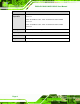
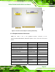
Connector Type Label
Ethernet connector RJ-45 LAN1
Ethernet connector RJ-45 LAN2
Keyboard/mouse PS/2 PT1
USB port USB port USB6
VGA port connector 15-pin female VGA1
Table 3-2: Rear Panel Connectors
3.2 Internal Peripheral Connectors
Internal peripheral connectors are found on the CPU card and are only accessible when
the CPU card is outside of the chassis. This section has complete descriptions of all the
internal, peripheral connectors on the PICOe-PV-D4251/N4551/D5251.
3.2.1 ATX Power Supply Enable Connector
CN Label: ATXCTL1
CN Type:
3-pin wafer (1x3)
CN Location:
See
Figure 3-3