
User guide

PICOe-PV-D4251/N4551/D5251 User Manual
Page 19
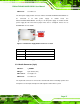
Pin Description
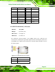
1 LCD Backlight Control
2 GROUND
3 +12V
4 GROUND
5 BACKLIGHT Enable
Table 3-5: Panel Backlight Connector Pinouts
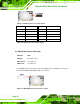
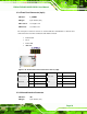
3.2.4 Battery Connector
CN Label: BAT1
CN Type:
2-pin wafer (1x2)
CN Location:
See
Figure 3-6
CN Pinouts:
See
Table 3-6
This is connected to the system battery. The battery provides power to the system clock to
retain the time when power is turned off.
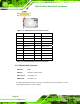
Figure 3-6: Battery Connector Location
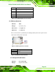
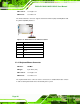
Pin Description
1 Battery+
2 Ground
Table 3-6: Battery Connector Pinouts
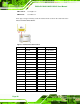
3.2.5 CompactFlash® Socket
CN Label: CF1 (solder side)
CN Type:
50-pin header (2x25)