
User guide

PICOe-PV-D4251/N4551/D5251 User Manual
Page 22
Pin Description
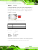
3 FANIO1
4 FANPWM1
Table 3-8: +12V Fan Connector Pinouts
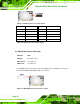
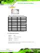
3.2.7 Digital Input/Output (DIO) Connector
CN Label: DIO1
CN Type:
10-pin header (2x5)
CN Location:
See
Figure 3-9
CN Pinouts:
See
Table 3-9
The digital input/output connector is managed through a Super I/O chip. The DIO
connector pins are user programmable.
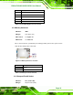
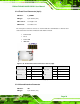
Figure 3-9: DIO Connector Location
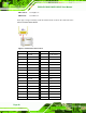
Pin Description Pin Description
1 GND 2 +5V
3 Output 3 4 Output 2
5 Output 1 6 Output 0
7 Input 3 8 Input 2
9 Input 1 10 Input 0
Table 3-9: DIO Connector Pinouts