PM-945GSE-N270 User Manual IEI Technology Corp. MODEL: PM-945GSE-N270 PCI-104 SBC with Intel® Atom N270 1.6 GHz CPU, Ethernet, USB 2.0, Audio, CF Card Type 2, RS-232, RS-422/485, IDE, RoHS Compliant User Manual Page i Rev. 1.
PM-945GSE-N270 User Manual Revision Date Version Changes 17 August, 2011 1.02 Minor revision to Figure 3-4: ATX Power Supply Enable Connector Location Updated formatting throughout document 26 March, 2010 1.01 Minor edit 28 August, 2009 1.
PM-945GSE-N270 User Manual Copyright COPYRIGHT NOTICE The information in this document is subject to change without prior notice in order to improve reliability, design and function and does not represent a commitment on the part of the manufacturer. In no event will the manufacturer be liable for direct, indirect, special, incidental, or consequential damages arising out of the use or inability to use the product or documentation, even if advised of the possibility of such damages.
PM-945GSE-N270 User Manual Table of Contents 1 INTRODUCTION........................................................................................................ 13 1.1 INTRODUCTION......................................................................................................... 14 1.1.1 Applications ..................................................................................................... 14 1.1.2 Benefits.................................................................................
PM-945GSE-N270 User Manual 3.2.9 LAN Connector ................................................................................................ 38 3.2.10 LCD Inverter Connector ................................................................................ 39 3.2.11 LED and +5V Output Connector ................................................................... 40 3.2.12 PCI-104 Connector........................................................................................ 41 3.2.
PM-945GSE-N270 User Manual 5.1 INTRODUCTION......................................................................................................... 74 5.1.1 Starting Setup................................................................................................... 74 5.1.2 Using Setup ...................................................................................................... 74 5.1.3 Getting Help...............................................................................................
PM-945GSE-N270 User Manual ROHS COMPLIANT UNDER 2002/95/EC WITHOUT MERCURY .....................................
PM-945GSE-N270 User Manual List of Figures Figure 1–1: PM-945GSE-N270 .....................................................................................................14 Figure 1-2: PM-945GSE-N270 Motherboard Overview ..............................................................16 Figure 1-3: PM-945GSE-N270 Motherboard Solder Side Overview .........................................17 Figure 1-4: PM-945GSE-N270 Dimensions (mm).......................................................................
PM-945GSE-N270 User Manual Figure 4-3: Clear BIOS Jumper Location ...................................................................................59 Figure 4-4: COM3 RS-232/422/RS485 Select Jumper Location................................................60 Figure 4-5: LVDS Voltage Select Jumper Location...................................................................61 Figure 4-6: PCI-104 Voltage Jumper Location...........................................................................
PM-945GSE-N270 User Manual List of Tables Table 1-1: PM-945GSE-N270 Specifications ..............................................................................22 Table 2-1: Package List Contents ...............................................................................................26 Table 2-2: Package List Contents (Optional Items)...................................................................26 Table 3-1: Peripheral Interface Connectors ......................................................
PM-945GSE-N270 User Manual Table 5-1: BIOS Navigation Keys ................................................................................................
PM-945GSE-N270 User Manual BIOS Menus BIOS Menu 1: Main .......................................................................................................................76 BIOS Menu 2: Advanced ..............................................................................................................78 BIOS Menu 3: CPU Configuration ...............................................................................................78 BIOS Menu 4: IDE Configuration.......................................
PM-945GSE-N270 User Manual Chapter 1 1 Introduction Page 13
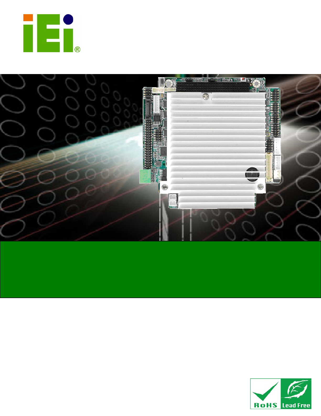
PM-945GSE-N270 User Manual 1.1 Introduction Figure 1–1: PM-945GSE-N270 The PCI-104 form factor PM-945GSE-N270 is a highly integrated embedded computer specifically optimized for multi-media applications requiring minimum installation space. The PM-945GSE-N270 is particularly suitable for low power and fan-less applications. The PM-945GSE-N270 supports a full range of functions for an AT compatible industrial computer in a space-saving 109 mm x 116 mm profile.
PM-945GSE-N270 User Manual ranging from 0°C to 60°C Rebooting automatically if the BIOS watchdog timer detects that the system is no longer operating 1.1.3 Features Some of the PM-945GSE-N270 motherboard features are listed below: Complies with RoHS Supports Intel® Atom™ N270 CPU Supports a maximum front side bus (FSB) speed up to 533MHz 1 GB on-board DDR 533 SDRAM Complete I/O support with SATA, CF Type II, PCI-104, LAN, and 4 x USB2.
PM-945GSE-N270 User Manual 1.
PM-945GSE-N270 User Manual Figure 1-3: PM-945GSE-N270 Motherboard Solder Side Overview 1.2.1 Connectors The PM-945GSE-N270 motherboard has the following connectors on-board (described in Chapter 3): 1 x AT/ATX 12V/5V connector 1 x CompactFlash® connector (solder side) 1 x Digital I/O connector 1 x Audio connector (supported via optional 5.1 channel audio kit with Realtek ALC655 AC'97 codec or 7.
PM-945GSE-N270 User Manual Page 18 1 x LED connector 1 x LVDS LCD connector 1 x PCI-104 connector 4 x RS-232 connectors 1 x RS-422/485 connector (shared with COM2) 1 x SATA connector 4 x USB connectors 1 x VGA connector
PM-945GSE-N270 User Manual 1.3 Dimensions The dimensions of the board are listed below: Length: 116 mm Width: 108.
PM-945GSE-N270 User Manual 1.4 Data Flow The PM-945GSE-N270 motherboard comes with an Intel® Atom™ N270 processor and an Intel® 945GSE Northbridge. Figure 1-5 shows the data flow between the system chipset, the CPU and other components installed on the motherboard. Figure 1-5: Data Flow Block Diagram 1.4.1 Technical Specifications PM-945GSE-N270 motherboard technical specifications are listed in the table below.
PM-945GSE-N270 User Manual Specification/Model PM-945GSE-N270 Form Factor PCI-104 Module CPU Intel® Atom™ N270 1.6 GHz with 533 MHz FSB Integrated Graphics Intel® 945GSE Memory 1 GB DDR2 SDRAM on-board (8 x 64 MB x16) System Controller Hub Chipset Intel® ICH7M BIOS AMI BIOS Compatible OS Microsoft Windows XP SP2 Microsoft Windows Vista Business (32bit) Linux Ubuntu 8.
PM-945GSE-N270 User Manual Specification/Model PM-945GSE-N270 Serial Four RS-232 One RS-422/485 (shared with COM2) USB 2.0/1.1 Four USB 2.0 Storage SATA One SATA connector CF One CF card slot Environmental and Power Specifications Power Supply 5V only, AT/ATX support Power Consumption 5 V @ 2.6A (Intel® Atom™ N270 1.6 GHz with on-board 1 GB DDR2) Operating temperature 0ºC ~ 60ºC Humidity 5% ~ 95% (non-condensing) Physical Specifications Dimensions 108.59 mm x 115.
PM-945GSE-N270 User Manual Chapter 2 2 Unpacking Page 23
PM-945GSE-N270 User Manual 2.1 Anti-static Precautions WARNING: Failure to take ESD precautions during the installation of the PM-945GSE-N270 may result in permanent damage to the PM-945GSE-N270 and severe injury to the user. Electrostatic discharge (ESD) can cause serious damage to electronic components, including the PM-945GSE-N270. Dry climates are especially susceptible to ESD.
PM-945GSE-N270 User Manual 2.3 Unpacking Checklist NOTE: If some of the components listed in the checklist below are missing, please do not proceed with the installation. Contact the IEI reseller or vendor you purchased the PM-945GSE-N270 from or contact an IEI sales representative directly. To contact an IEI sales representative, please send an email to sales@iei.com.tw. 2.3.
PM-945GSE-N270 User Manual 2 Dual USB cable (without bracket) (P/N: 32000-070301-RS) 1 VGA cable (P/N:32000-033804-RS) 1 Mini jumper pack 1 Quick Installation Guide 1 Utility CD Table 2-1: Package List Contents 2.4 Optional Items ATX power cable (P/N: 32100-052100-RS) SATA power cable (P/N: 32100-068600-RS) RS-422/485 Cable (P/N: 32200-074800-RS) 5.1 channel AC'97 audio kit with Realtek ALC655 codec (P/N: AC-KIT08R-R10) 7.
PM-945GSE-N270 User Manual Chapter 3 3 Connectors Page 27
PM-945GSE-N270 User Manual 3.1 Peripheral Interface Connectors The locations of the peripheral interface connectors are shown in Section 3.1.1. A complete list of all the peripheral interface connectors can be seen in Section 3.1.2. 3.1.1 PM-945GSE-N270 Motherboard Layout Figure 3-1 shows the on-board peripheral connectors and jumpers on the front side of the board. Figure 3-1: Connector and Jumper Locations (Front Side) Figure 3-2 shows the onboard peripheral connectors on the solder side of the board.
PM-945GSE-N270 User Manual Figure 3-2: Connector and Jumper Locations (Solder Side) 3.1.2 Peripheral Interface Connectors The table below shows a list of the peripheral interface connectors on the PM-945GSE-N270 motherboard. Detailed descriptions of these connectors can be found in the following section.
PM-945GSE-N270 User Manual Connector Type Label LCD inverter connector 5-pin wafer connector INVERTER1 LED and +5V output connector 6-pin wafer LED_C1 LVDS LCD connector 30-pin crimp connector LVDS1 PCI/104 connector 120-pin socket PC104_PLUS1 Power button connector 2-pin wafer PWRBTN1 Reset button connector 2-pin wafer RESET1 RS-232 Serial ports 1-4 connector 40-pin box header CN2 RS-422/85 Serial port connector 4-pin box header CN4 SATA drive connector 7-pin SATA drive connecto
PM-945GSE-N270 User Manual Figure 3-3: 12V / 5V Power Connector Location PIN NO. DESCRIPTION 1 VCC12 2 GND 3 VCC5 Table 3-2: 12V / 5V Power Connector Pinouts 3.2.2 ATX Power Supply Enable Connector CN Label: ATXCTL1 CN Type: 3-pin wafer (1x3) CN Location: See Figure 3-4 CN Pinouts: See Table 3-3 The connector is for enabling an ATX power supply. When connected to the power supply, the power can be turned on and off with the front panel switch. Use the optional ATX power cable.
PM-945GSE-N270 User Manual Figure 3-4: ATX Power Supply Enable Connector Location Pin Description 1 +5 V Standby 2 GND 3 PS-ON# Table 3-3: ATX Power Supply Enable Connector Pinouts 3.2.3 Audio Kit Connector CN Label: CN7 CN Type: 9-pin header CN Location: See Figure 3-5 CN Pinouts: See Table 3-4 This connector connects to an external audio kit.
PM-945GSE-N270 User Manual Figure 3-5: Audio Kit Connector Location Pin Description Pin Description 1 SYNC 2 BITCLK 3 SDOUT 4 PCBEEP 5 SDIN 6 RST# 7 VCC 8 GND 9 +12 V Table 3-4: Audio Kit Connector Pinouts 3.2.4 Battery Connector CN Label: BAT1 CN Type: 2-pin wafer connector CN Location: See Figure 3-6 CN Pinouts: See Table 3-5 This battery connector connects to an externally mounted 3V, Lithium, cell coin battery (VARTA CR2032).
PM-945GSE-N270 User Manual disposal instructions. Do not dispose of a used battery with normal household waste. WARNING! 1. Keep batteries away from children. 2. There is a danger of explosion if the battery is incorrectly replaced. 3. Only a certified module from IEI can be used as a replacement. 4. Do not expose the battery to excessive heat or fire. 5. If the battery shows signs of leakage, contact a local vendor or IEI immediately. Figure 3-6: Battery Connector Location PIN NO.
PM-945GSE-N270 User Manual Figure 3-7: CompactFlash® Connector Location PIN NO. DESCRIPTION PIN NO.
PM-945GSE-N270 User Manual 43 INPACK# 44 REG# 45 BVD2 46 BVD1 47 D8 48 D9 49 D10 50 GND Table 3-6: CompactFlash® Connector Pinouts 3.2.6 Fan Connector CN Label: CPU_FAN1 CN Type: 3-pin header CN Location: See Figure 3-8 CN Pinouts: See Table 3-7 The fan connector attaches to a cooling fan. Figure 3-8: Fan Connector Location PIN NO.
PM-945GSE-N270 User Manual 3.2.7 Digital I/O Connector CN Label: CN5 CN Type: 10-pin header CN Location: See Figure 3-9 CN Pinouts: See Table 3-8 The digital I/O connector provides programmable input and output for external devices. The digital I/O provides 4-bit output and 4-bit input. Figure 3-9: Digital I/O Connector Locations PIN NO. DESCRIPTION PIN NO.
PM-945GSE-N270 User Manual CN Pinouts: See Figure 3-10 CN Location: See Table 3-9 The keyboard and mouse connector can be connected to a standard PS/2 cable or PS/2 Y-cable to add keyboard and mouse functionality to the system. Figure 3-10: Keyboard/Mouse Connector Location PIN NO. DESCRIPTION 1 VCC5 2 MOUSE DATA 3 MOUSE CLOCK 4 KEYBOARD DATA 5 KEYBOARD CLOCK 6 GND Table 3-9: Keyboard/Mouse Connector Pinouts 3.2.
PM-945GSE-N270 User Manual The PM-945GSE-N270 is equipped with an Ethernet controller. The Ethernet controller is interfaced to the external LAN by direct connection to the LAN connection or by connecting the LAN connector to an RJ-45 interface connector. Figure 3-11: LAN Connector Location PIN DESCRIPTION PIN DESCRIPTION 1 VCC3.3 6 Active 2 RX+ 7 RX- 3 Link 8 GND 4 N/C 9 GND 5 TX+ 10 TX- Table 3-10: LAN Connector Pinouts 3.2.
PM-945GSE-N270 User Manual Figure 3-12: LCD Inverter Connector Location PIN NO. DESCRIPTION 1 LCD_BKLTCTL 2 GROUND 3 VCC12 4 GROUND 5 LCD_BKLEN Table 3-11: LCD Inverter Connector Pinouts 3.2.11 LED and +5V Output Connector CN Label: LED_C1 CN Type: 6-pin wafer (1x6) CN Location: See Figure 3-13 CN Pinouts: See Table 3-12 The LED and +5V output connector connects to the hard drive activity LED and power LED on the system front panel and provides a +5V power output.
PM-945GSE-N270 User Manual Figure 3-13: LED Connector Locations PIN NO. DESCRIPTION 1 +5 V 2 GND 3 Power LED+ 4 Power LED- 5 HDD LED+ 6 HDD LED- Table 3-12: LED Connector Pinouts 3.2.12 PCI-104 Connector CN Label: PC104_PLUS1 CN Type: 120-pin socket CN Location: See Figure 3-14 CN Pinouts: See Table 3-13 The PCI-104 connector is for installing a PCI-104 expansion card.
PM-945GSE-N270 User Manual Figure 3-14: PCI-104 Connector Location Pin No. Column A Column B Column C Column D 1 GND/5 V TBD1 5V AD00 2 VI/O1 AD02 AD01 +5 V 3 AD05 GND AD04 AD03 4 C/BE0# AD07 GND AD06 5 GND AD09 AD08 GND 6 AD11 VI/O2 AD10 M66EN 7 AD14 AD13 GND AD12 8 +3.3 V C/BE1# AD15 +3.3 V 9 SERR# GND SB0# PAR 10 GND PERR# +3.3 V SDONE 11 STOP# +3.3 V LOCK# GND 12 +3.3 V TRDY# GND DEVSEL# 13 FRAME# GND IRDY# +3.3 V 14 GND AD16 +3.
PM-945GSE-N270 User Manual Pin No. Column A Column B Column C Column D 17 +3.3 V AD23 AD22 +3.3 V 18 IDSEL0 GND IDSEL1 IDSEL2 19 AD24 C/BE3# VI/O1 IDSEL3 20 GND AD26 AD25 GND 21 AD29 +5 V AD28 AD27 22 +5 V AD30 GND AD31 23 REQ0# GND REQ1# VI/O2 24 GND REQ2# +5 V GNT0# 25 GNT1# VI/O3 GNT2# GND 26 +5 V CLK0 GND CLK1 27 CLK2 +5 V CLK3 GND 28 GND INTD# +5 V RST# 29 +12 V INTA# INTB# INTC# 30 -12 V TBD2 TBD GND/3.
PM-945GSE-N270 User Manual Figure 3-15: Power Button Connector Location PIN NO. DESCRIPTION 1 Power Switch 2 GND Table 3-14: Power Button Connector Pinouts 3.2.14 Reset Button Connector CN Label: RESET1 CN Type: 2-pin wafer (1x2) CN Location: See Figure 3-16 CN Pinouts: See Table 3-15 The reset button connector is connected to a reset switch on the system chassis.
PM-945GSE-N270 User Manual PIN NO. DESCRIPTION 1 Reset Switch 2 GND Table 3-15: Reset Button Connector Pinouts 3.2.15 RS-232 Serial Port Connectors CN Label: CN2 CN Type: 40-pin header CN Location: See Figure 3-17 CN Pinouts: See Table 3-16 The serial ports connector connects to RS-232 serial port devices. Figure 3-17: RS-232 Serial Port Connector Locations PIN NO. DESCRIPTION PIN NO.
PM-945GSE-N270 User Manual 15 TX2 16 CTS2# 17 DTR2# 18 RI2# 19 GND 20 GND 21 DCD3# 22 DSR3# 23 RX3 24 RTS3# 25 TX3 26 CTS3# 27 DTR3# 28 RI3# 29 GND 30 GND 31 DCD4# 32 DSR4# 33 RX4 34 RTS4# 35 TX4 36 CTS4# 37 DTR4# 38 RI4# 39 GND 40 GND Table 3-16: RS-232 Serial Port Connector Pinouts 3.2.
PM-945GSE-N270 User Manual PIN NO. DESCRIPTION 1 RXD485# 2 RXD485+ 3 TXD485+ 4 TXD485# Table 3-17: RS-422/RS-485 Serial Port Connector Pinouts 3.2.17 LVDS LCD Connector CN Label: LVDS1 CN Type: 30-pin crimp connector CN Location: See Figure 3-19 CN Pinouts: See Table 3-18 The LVDS connector is connected to a LVDS LCD display device.
PM-945GSE-N270 User Manual Pin Description Pin Description 11 N/C 12 N/C 13 GROUND 14 GROUND 15 LVDSB_Y0+ 16 LVDSB_Y0- 17 LVDSB_Y1+ 18 LVDSB_Y1- 19 LVDSB_Y2+ 20 LVDSB_Y2- 21 LVDSB_CLK+ 22 LVDSB_CLK- 23 N/C 24 N/C 25 GROUND 26 GROUND 27 VCC_LVDS 28 VCC_LVDS 29 VCC_LVDS 30 VCC_LVDS Table 3-18: LVDS Connector Pinouts 3.2.
PM-945GSE-N270 User Manual PIN NO. DESCRIPTION 1 GND 2 TX+ 3 TX- 4 GND 5 RX- 6 RX+ 7 GND Table 3-19: SATA Drive Connector Pinouts 3.2.19 SPI Flash Connector CN Label: JSPI1 CN Type: 6-pin header (1x6) CN Location: See Figure 3-21 CN Pinouts: See Table 3-20 The 6-pin SPI Flash connector is used to flash the BIOS.
PM-945GSE-N270 User Manual PIN DESCRIPTION PIN DESCRIPTION Table 3-20: SPI Flash Connector 3.2.20 USB Connector CN Label: CN9 and CN10 CN Type: 8-pin header (2x4) CN Location: See Figure 3-22 CN Pinouts: See Table 3-21 The 2x4 USB pin connectors provide connectivity to USB 2.0 ports. Each USB connector can support two USB devices. The USB port is used for I/O bus expansion. Figure 3-22: USB Connector Pinout Locations PIN NO. DESCRIPTION PIN NO.
PM-945GSE-N270 User Manual CN Type: 10-pin box header CN Location: See Figure 3-23 CN Pinouts: See Table 3-22 The VGA connector connects to a monitor. Figure 3-23: VGA Connector Location PIN NO. DESCRIPTION PIN NO.
PM-945GSE-N270 User Manual Chapter 4 4 Installation Page 52
PM-945GSE-N270 User Manual 4.1 Anti-static Precautions WARNING: Failure to take ESD precautions during the installation of the PM-945GSE-N270 may result in permanent damage to the PM-945GSE-N270 and severe injury to the user. Electrostatic discharge (ESD) can cause serious damage to electronic components, including the PM-945GSE-N270. Dry climates are especially susceptible to ESD.
PM-945GSE-N270 User Manual 4.2 Installation Considerations NOTE: The following installation notices and installation considerations should be read and understood before the PM-945GSE-N270 is installed. All installation notices should be strictly adhered to. Failing to adhere to these precautions may lead to severe damage of the PM-945GSE-N270 and injury to the person installing the motherboard. 4.2.
PM-945GSE-N270 User Manual o When working with the PM-945GSE-N270, make sure that it is disconnected from all power supplies and that no electricity is being fed into the system. Before and during the installation of the PM-945GSE-N270 DO NOT: Remove any of the stickers on the PCB board. These stickers are required for warranty validation. Use the product before verifying all the cables and power connectors are properly connected.
PM-945GSE-N270 User Manual WARNING: A CPU should never be turned on without its heat sink being installed. If the heat sink is removed and the system turned on, permanent damage to the CPU, PM-945GSE-N270 and other electronic components attached to the system may be incurred. Running a CPU without a heat sink may also result in injury to the user. 4.3 Unpacking When the PM-945GSE-N270 is unpacked, please do the following: Follow the anti-static precautions outlined in Section 4.1.
PM-945GSE-N270 User Manual Step 1: Turn the CPU board over so that the CF Type II card socket is facing up. Step 2: Gently push the CF Type II card into the socket until it clicks into place. (See Figure 4-1) Figure 4-1: CompactFlash® Card Installation 4.5 Jumper Settings NOTE: A jumper is a metal bridge that is used to close an electrical circuit. It consists of two metal pins and a small metal clip (protected by a plastic cover) that slides over the pins to connect them.
PM-945GSE-N270 User Manual Before the PM-945GSE-N270 is installed in the system, the jumpers must be set in accordance with the desired configuration. There are three jumpers on the PM-945GSE-N270. These three jumpers are listed in the table below.
PM-945GSE-N270 User Manual 4.5.1 Clear CMOS Jumper Jumper Label: J_CMOS1 Jumper Type: 3-pin header Jumper Settings: See Table 4-1 Jumper Location: See Figure 4-3 To reset the BIOS, move the jumper to the "Clear BIOS" position for 3 seconds or more, then move back to the default position. Setting Description 1-2 Keep current BIOS setup 2-3 Clear BIOS Table 4-1: Clear BIOS Jumper Settings Figure 4-3: Clear BIOS Jumper Location 4.5.
PM-945GSE-N270 User Manual Setting DESCRIPTION 1-2 RS-232 (Default) 3-4 RS-422 5-6 RS-485 7-8 RS-485 with RTS# control Table 4-2: COM3 RS-232/422/RS485 Select Jumper Settings Figure 4-4: COM3 RS-232/422/RS485 Select Jumper Location 4.5.3 LVDS Voltage Select Jumper Jumper Label: J_LVDS1 Jumper Type: 3-pin header Jumper Location: See Figure 4-2 Jumper Settings: See Table 4-3 The LVDS Voltage Select jumper sets the LVDS voltage to +3.3V or +5V. JP1 DESCRIPTION 1-2 LCD/VCC +3.
PM-945GSE-N270 User Manual Figure 4-5: LVDS Voltage Select Jumper Location 4.5.4 PCI-104 Voltage Setup Jumper Label: JP2 Jumper Type: 3-pin header Jumper Settings: See Table 4-4 Jumper Location: See Figure 4-6 This jumper selects the voltage supplied to the PCI-104 expansion module. Setting Description 1-2 +5.0 V 2-3 +3.
PM-945GSE-N270 User Manual 4.6 Chassis Installation WARNING: Airflow is critical to the cooling of the CPU and other onboard components. The chassis in which the PM-945GSE-N270 must have air vents to allow cool air to move into the system and hot air to move out. The PM-945GSE-N270 must be installed in a chassis with ventilation holes on the sides allowing air to flow through the heat sink surface.
PM-945GSE-N270 User Manual Separately purchased optional IEI items that can be installed are listed below: ATX power cable 5.1 AC’97 Audio kit 7.1 HD Audio kit SATA power cable For more details about the items listed above, please refer to Chapter 2.4. Installation of the accessories listed above is described in detail below. 4.7.1 Keyboard/Mouse Y-cable Connector The PM-945GSE-N270-R11 is shipped with a keyboard/mouse Y-cable connector.
PM-945GSE-N270 User Manual Figure 4-7: Keyboard/mouse Y-cable Connection Step 6: Attach PS/2 connectors to the chassis. The keyboard/mouse Y-cable connector is connected to two PS/2 connectors. To secure the PS/2 connectors to the chassis please refer to the installation instructions that came with the chassis. Step 7: Connect the keyboard and mouse. Once the PS/2 connectors are connected to the chassis, a keyboard and mouse can each be connected to one of the PS/2 connectors.
PM-945GSE-N270 User Manual Step 2: Insert the cable connector. Insert the connector from the LVDS PCB driving board to the LVDS connector as shown in Figure 4-8. When connecting the connectors, make sure the pins are properly aligned. WARNING: The diagram below is merely for illustration. The configuration and connection of the cables from the TFT LCD screen being installed may be different. Please refer to the installation manual that came with the TFT LCD screen.
PM-945GSE-N270 User Manual Figure 4-9: Backlight Inverter Connection 4.7.3 SATA Drive Connection The PM-945GSE-N270 is shipped with two SATA drive cables and one SATA drive power cable. To connect the SATA drives to the connectors, please follow the steps below. Step 1: Locate the connectors. The locations of the SATA drive connectors are shown in Chapter 3. Step 2: Insert the cable connector.
PM-945GSE-N270 User Manual Figure 4-10: SATA Drive Cable Connection Step 3: Connect the cable to the SATA disk. Connect the connector on the other end of the cable to the connector at the back of the SATA drive. See Figure 4-11. Step 4: Connect the SATA power cable. Connect the SATA power connector to the back of the SATA drive. See Figure 4-11.
PM-945GSE-N270 User Manual Figure 4-11: SATA Power Drive Connection 4.7.4 Four Serial Port Connector The 40-pin serial port connector connects the board connector to four DB-9 connectors. To install, please follow the steps below. Step 1: Locate the COM connector. The locations of the COM port connectors are shown in Chapter 4. Step 2: Insert the cable connector. Align the cable connector with the onboard connector. Make sure pin 1 on the board and connector line up Figure 4-12.
PM-945GSE-N270 User Manual Figure 4-12: Four Serial Port Connector Step 3: Secure the serial ports to the chassis. Tighten the screws on the DB-9 connectors to secure them to the chassis.Step 0: Figure 4-13: Serial Device Connector 4.7.5 USB Cable (Dual Port without Bracket) The PM-945GSE-N270 is shipped with a dual port USB 2.0 cable. To connect the USB cable connector, please follow the steps below. Step 1: Locate the connectors. The locations of the USB connectors are shown in Chapter 3.
PM-945GSE-N270 User Manual WARNING: If the USB pins are not properly aligned, the USB device can burn out. Step 2: Align the connectors. The cable has two connectors. Correctly align pin 1on each cable connector with pin 1 on the PM-945GSE-N270 USB connector. Step 3: Insert the cable connectors. Once the cable connectors are properly aligned with the USB connectors on the PM-945GSE-N270, connect the cable connectors to the on-board connectors. See Figure 4-14.
PM-945GSE-N270 User Manual NOTE: If the installation program doesn't start automatically: Click "Start->My Computer->CD Drive->autorun.exe" Step 2: The driver main menu appears (Figure 4-15). Figure 4-15: Introduction Screen Step 3: Click PM-945GSE-N270. Step 4: Select OS. Step 5: A new screen with a list of available drivers appears (Figure 4-16).
PM-945GSE-N270 User Manual Figure 4-16: Available Drivers Step 6: Install all of the necessary drivers in this menu.
PM-945GSE-N270 User Manual Chapter 5 5 BIOS Page 73
PM-945GSE-N270 User Manual 5.1 Introduction The BIOS is programmed onto the BIOS chip. The BIOS setup program allows changes to certain system settings. This chapter outlines the options that can be changed. 5.1.1 Starting Setup The AMI BIOS is activated when the computer is turned on. The setup program can be activated in one of two ways. 1. Press the DELETE key as soon as the system is turned on or 2. Press the DELETE key when the “Press Del to enter SETUP” message appears on the screen. 0.
PM-945GSE-N270 User Manual Key Function F2 /F3 key Change color from total 16 colors. F2 to select color forward. F10 key Save all the CMOS changes, only for Main Menu Table 5-1: BIOS Navigation Keys 5.1.3 Getting Help When F1 is pressed a small help window describing the appropriate keys to use and the possible selections for the highlighted item appears. To exit the Help Window press ESC or the F1 key again. 5.1.
PM-945GSE-N270 User Manual 5.2 Main The Main BIOS menu (BIOS Menu 1) appears when the BIOS Setup program is entered. The Main menu gives an overview of the basic system information. Main Advanced PCIPNP BIOS SETUP UTILITY Boot Security Chipset System Overview AMIBIOS Version :08.00.15 Build Date :05/26/09 ID: :B162MR12 Exit Use [ENTER], [TAB] or [SHIFT-TAB] to select a field. Use [+] or [-] to configure system time. Processor Genuine Intel® CPU N270 @ 1.
PM-945GSE-N270 User Manual The System Overview field also has two user configurable fields: System Time [xx:xx:xx] Use the System Time option to set the system time. Manually enter the hours, minutes and seconds. System Date [xx/xx/xx] Use the System Date option to set the system date. Manually enter the day, month and year. 5.
PM-945GSE-N270 User Manual Main Advanced PCIPNP BIOS SETUP UTILITY Boot Security Chipset Advanced Settings WARNING: Setting wrong values in below sections may cause system to malfunction > > > > > > > Exit Configure CPU CPU Configuration IDE Configuration SuperIO Configuration Hardware Health Configuration Power Configuration Remote Access Configuration USB Configuration Select Screen Select Item Enter Go to SubScreen F1 General Help F10 Save and Exit ESC Exi
PM-945GSE-N270 User Manual Brand String: Lists the brand name of the CPU being used Frequency: Lists the CPU processing speed Cache L1: Lists the CPU L1 cache size Cache L2: Lists the CPU L2 cache size 5.3.2 IDE Configuration Use the IDE Configuration menu (BIOS Menu 4) to change and/or set the configuration of the IDE devices installed in the system.
PM-945GSE-N270 User Manual Enhanced Configures the on-board ATA/IDE controller to be in DEFAULT Enhanced mode. In this mode, IDE channels and SATA channels are separated. This mode supports up to 6 storage devices. Some legacy OS do not support this mode. Legacy IDE Channels [PATA Pri, SATA Sec] SATA Only PATA Pri, SATA Sec Only the SATA drives are enabled. DEFAULT The IDE drives are enabled on the Primary IDE channel. The SATA drives are enabled on the Secondary IDE channel.
PM-945GSE-N270 User Manual Disabled Enabled DEFAULT Allows hard disks to be overwritten Prevents hard disks from being overwritten 5.3.2.1 IDE Master, IDE Slave Use the IDE Master and IDE Slave configuration menu to view both primary and secondary IDE device details and configure the IDE devices connected to the system.
PM-945GSE-N270 User Manual interrupt if block mode is not used. Block mode allows transfers of up to 64 KB per interrupt. PIO Mode: Indicates the PIO mode of the installed device. Async DMA: Indicates the highest Asynchronous DMA Mode that is supported. Ultra DMA: Indicates the highest Synchronous DMA Mode that is supported. S.M.A.R.T.: Indicates whether or not the Self-Monitoring Analysis and Reporting Technology protocol is supported. 32Bit Data Transfer: Enables 32-bit data transfer.
PM-945GSE-N270 User Manual BIOS is prevented from using the LBA mode control on Disabled the specified channel. Auto DEFAULT BIOS auto detects the LBA mode control on the specified channel. Block (Multi Sector Transfer) [Auto] Use the Block (Multi Sector Transfer) to disable or enable BIOS to auto detect if the device supports multi-sector transfers. BIOS is prevented from using Multi-Sector Transfer on the Disabled specified channel.
PM-945GSE-N270 User Manual PIO mode 4 selected with a maximum transfer rate of 16.6 MB/s 4 (This setting generally works with all hard disk drives manufactured after 1999. For other disk drives, such as IDE CD-ROM drives, check the specifications of the drive.) DMA Mode [Auto] Use the DMA Mode BIOS selection to adjust the DMA mode options. Auto DEFAULT BIOS auto detects the DMA mode. Use this value if the IDE disk drive support cannot be determined.
PM-945GSE-N270 User Manual Ultra DMA mode 3 selected with a maximum data transfer UDMA3 rate of 44 MB/s (To use this mode, it is required that an 80-conductor ATA cable is used.) Ultra DMA mode 4 selected with a maximum data transfer UDMA4 rate of 66.6 MB/s (To use this mode, it is required that an 80-conductor ATA cable is used.) Ultra DMA mode 5 selected with a maximum data transfer UDMA5 rate of 99.9 MB/s (To use this mode, it is required that an 80-conductor ATA cable is used.) S.M.
PM-945GSE-N270 User Manual Main Advanced BIOS SETUP UTILITY Boot Security PCIPNP Chipset Configure SCH3114 Super I/O Chipset Serial Port1 Address [3F8] Serial Port1 IRQ [IRQ4] Serial Port2 Address [2F8] Serial Port2 IRQ [IRQ3] Serial Port3 Address [3E8] Serial Port3 IRQ [IRQ4] Select RS-232 or RS-422/485 [RS-232] Serial Port4 Address [2E8] Serial Port4 IRQ [IRQ3] Exit Allows BIOS to select Serial Port Base Addresses Enter F1 F10 ESC Select Screen Select Item
PM-945GSE-N270 User Manual Disabled 2F8 No base address is assigned to Serial Port 2 Serial Port 2 I/O port address is 3F8 and the interrupt DEFAULT address is IRQ3 3E8 Serial Port 2 I/O port address is 3E8 and the interrupt address is IRQ4 2E8 Serial Port 2 I/O port address is 2E8 and the interrupt address is IRQ3 Serial Port2 IRQ [3] Use the Serial Port3 IRQ option to select the interrupt address for serial port 3.
PM-945GSE-N270 User Manual 4 Serial port 3 IRQ address is 4 Serial Port4 Address [2E8] Use the Serial Port4 Address option to select the base addresses for serial port 4.
PM-945GSE-N270 User Manual Main Advanced PCIPNP BIOS SETUP UTILITY Boot Security Chipset Exit Hardware Health Configuration CPU Temperature Sensor SYS1 Temperature Sensor :52ºC/125ºF :44ºC/111ºF CPU_Fan1 :N/A VCC_CORE +5V +12V +1.8V VCC VSB VBAT :1.184 V :4.918 V :12.144 V :1.776 V :3.280 V :3.408 V :3.280 V Enter F1 F10 ESC Select Screen Select Item Go to SubScreen General Help Save and Exit Exit v02.61 ©Copyright 1985-2006, American Megatrends, Inc.
PM-945GSE-N270 User Manual 5.3.5 Power Configuration The Power Configuration menu (BIOS Menu 8) allows the advanced power management options to be configured. Main Advanced PCIPNP BIOS SETUP UTILITY Boot Security Current Jumper Setting [AT Power] Chipset Exit Go into On/Off, or Suspend when Power button is pressed Enter F1 F10 ESC Select Screen Select Item Go to SubScreen General Help Save and Exit Exit v02.61 ©Copyright 1985-2006, American Megatrends, Inc.
PM-945GSE-N270 User Manual Main Advanced PCIPNP BIOS SETUP UTILITY Boot Security Chipset Exit Configure Remote Access type and parameters Remote Access [Disabled] Serial port number Base Address, IRQ Serial Port Mode Redirection After BIOS POST Terminal Type [COM1] [3F8H, 3] [115200 8,n,1] [Always] [ANSI] Enter F1 F10 ESC Select Screen Select Item Go to SubScreen General Help Save and Exit Exit v02.61 ©Copyright 1985-2006, American Megatrends, Inc.
PM-945GSE-N270 User Manual 1 2 System is remotely accessed through COM2 3 System is remotely accessed through COM3 4 System is remotely accessed through COM4 System is remotely accessed through COM1 DEFAULT NOTE: Make sure the selected COM port is enabled through the Super I/O configuration menu. Base Address, IRQ [3F8h,4] The Base Address, IRQ option cannot be configured and only shows the interrupt address of the serial port listed above.
PM-945GSE-N270 User Manual Disabled The console is not redirected after POST Boot Loader Redirection is active during POST and during Boot Loader Always DEFAULT Redirection is always active (Some OSes may not work if set to Always) Terminal Type [ANSI] Use the Terminal Type BIOS option to specify the remote terminal type. ANSI VT100 The target terminal type is VT100 VT-UTF8 The target terminal type is VT-UTF8 DEFAULT The target terminal type is ANSI 5.3.
PM-945GSE-N270 User Manual USB Configuration The USB Configuration field shows the system USB configuration. The items listed are: Module Version: x.xxxxx.xxxxx USB Devices Enabled The USB Devices Enabled field lists the USB devices that are enabled on the system USB 1.1 Controller [Enabled] Use the USB Function BIOS option to enable or disable USB function support. Disabled Enabled USB 1.1 controller disabled DEFAULT USB 1.1 controller enabled USB 2.
PM-945GSE-N270 User Manual Legacy USB support disabled if no USB devices are Auto connected 5.4 PCI/PnP Use the PCI/PnP menu (BIOS Menu 11) to configure advanced PCI and PnP settings. WARNING! Setting wrong values for the BIOS selections in the PCIPnP BIOS menu may cause the system to malfunction.
PM-945GSE-N270 User Manual Available DEFAULT The specified IRQ is available to be used by PCI/PnP devices The specified IRQ is reserved for use by Legacy ISA Reserved devices Available IRQ addresses are: IRQ3 IRQ4 IRQ5 IRQ7 IRQ9 IRQ10 IRQ 11 IRQ 14 IRQ 15 DMA Channel# [Available] Use the DMA Channel# option to assign a specific DMA channel to a particular PCI/PnP device.
PM-945GSE-N270 User Manual 5.5 Boot Settings Configuration Use the Boot menu (BIOS Menu 12) to configure system boot options. Main Advanced PCIPNP BIOS SETUP UTILITY Boot Security Chipset Boot Settings Configuration > Boot Settings Configuration > > > > Boot Device Priority Hard Disk Drives CD/DVD Drives Removable Drives Exit Configure settings during system boot.
PM-945GSE-N270 User Manual Quick Boot [Enabled] Use the Quick Boot BIOS option to make the computer speed up the boot process. Disabled Enabled No POST procedures are skipped DEFAULT Some POST procedures are skipped to decrease the system boot time Quiet Boot [Disabled] Use the Quiet Boot BIOS option to select the screen display when the system boots.
PM-945GSE-N270 User Manual On DEFAULT Allows the Number Lock on the keyboard to be enabled automatically when the computer system boots up. This allows the immediate use of the 10-key numeric keypad located on the right side of the keyboard. To confirm this, the Number Lock LED light on the keyboard is lit. Boot From LAN Support [Disabled] Use the BOOT From LAN Support option to enable the system to be booted from a remote system.
PM-945GSE-N270 User Manual 5.5.3 Hard Disk Drives Use the Hard Disk Drives menu to specify the boot sequence of the available HDDs. Only installed hard drives are shown. Main Advanced PCIPNP BIOS SETUP UTILITY Boot Security Chipset Hard Disk Drives > 1st Drive [Hard Drive 1] > 2nd Drive [Hard Drive 2] > 3rd Drive [Hard Drive 3] Exit Specifies the boot sequence from the available devices.
PM-945GSE-N270 User Manual Main Advanced PCIPNP BIOS SETUP UTILITY Boot Security Chipset Hard Disk Drives > 1st Drive [Removable Drive 1] > 2nd Drive [Removable Drive 2] > 3rd Drive [Removable Drive 3] Exit Specifies the boot sequence from the available devices. Enter F1 F10 ESC Select Screen Select Item Go to SubScreen General Help Save and Exit Exit v02.61 ©Copyright 1985-2006, American Megatrends, Inc. BIOS Menu 16: Removable Drives 5.5.
PM-945GSE-N270 User Manual Main Advanced PCIPNP BIOS SETUP UTILITY Boot Security Chipset Hard Disk Drives > 1st Drive [CD/DVD 1] > 2nd Drive [CD/DVD 2] > 3rd Drive [CD/DVD 3] Exit Specifies the boot sequence from the available devices. Enter F1 F10 ESC Select Screen Select Item Go to SubScreen General Help Save and Exit Exit v02.61 ©Copyright 1985-2006, American Megatrends, Inc. BIOS Menu 17: CD/DVD Drives 5.
PM-945GSE-N270 User Manual this field and enter the password. After the password has been added, Install appears next to Change Supervisor Password. Change User Password Use the Change User Password to set or change a user password. The default for this option is Not Installed. If a user password must be installed, select this field and enter the password. After the password has been added, Install appears next to Change User Password.
PM-945GSE-N270 User Manual Main Advanced PCIPNP BIOS SETUP UTILITY Boot Security Chipset Exit Advanced Chipset Settings WARNING: Setting wrong values in below section may cause system to malfunction. > Northbridge Configuration > Southbridge Configuration Enter F1 F10 ESC Select Screen Select Item Go to SubScreen General Help Save and Exit Exit v02.61 ©Copyright 1985-2006, American Megatrends, Inc. BIOS Menu 19: Chipset 5.7.
PM-945GSE-N270 User Manual Memory Hole [Disabled] Use the Memory Hole option to reserve memory space between 15 MB and 16 MB for ISA expansion cards that require a specified area of memory to work properly. If an older ISA expansion card is used, please refer to the documentation that came with the card to see if it is necessary to reserve the space.
PM-945GSE-N270 User Manual DVMT Mode DEFAULT Graphics memory is dynamically allocated according to the system and graphics needs. A fixed portion of graphics memory is reserved as Combo Mode graphics memory. If more memory is needed, graphics memory is dynamically allocated according to the system and graphics needs. DVMT/FIXED Memory [128 MB] Use the DVMT/FIXED Memory option to specify the maximum amount of memory that can be allocated as graphics memory.
PM-945GSE-N270 User Manual 1280 x 1024 36b 1400 x 1050 36b 1440 x 900 36b 1600 x 1200 36b 5.7.2 Southbridge Configuration Use the Southbridge Configuration menu (BIOS Menu 21) to configure the audio controller and spread spectrum function of the Southbridge chipset.
PM-945GSE-N270 User Manual modulates changes in the extreme values from spikes to flat curves, thus reducing the EMI. This benefit may in some cases be outweighed by problems with timing-critical devices, such as a clock-sensitive SCSI device. Disabled DEFAULT Enabled EMI not reduced EMI reduced 5.8 Exit Use the Exit menu (BIOS Menu 22) to load default BIOS values, optimal failsafe values and to save configuration changes.
PM-945GSE-N270 User Manual Discard Changes Use the Discard Changes option to discard the changes and remain in the BIOS configuration setup program. Load Optimal Defaults Use the Load Optimal Defaults option to load the optimal default values for each of the parameters on the Setup menus. F9 key can be used for this operation. Load Failsafe Defaults Use the Load Failsafe Defaults option to load failsafe default values for each of the parameters on the Setup menus.
PM-945GSE-N270 User Manual Appendix A A BIOS Options Page 110
PM-945GSE-N270 User Manual Below is a list of BIOS configuration options in the BIOS chapter. System Overview .................................................................................................................76 System Time [xx:xx:xx] .......................................................................................................77 System Date [xx/xx/xx] ........................................................................................................
PM-945GSE-N270 User Manual USB Devices Enabled..........................................................................................................94 USB 1.1 Controller [Enabled]..............................................................................................94 USB 2.0 Controller [Enabled]..............................................................................................94 Legacy USB Support [Enabled]...............................................................................
PM-945GSE-N270 User Manual Appendix B B Terminology Page 113
PM-945GSE-N270 User Manual ACPI Advanced Configuration and Power Interface (ACPI) is an OS-directed configuration, power management, and thermal management interface. AHCI Advanced Host Controller Interface (AHCI) is a SATA Host controller register-level interface. ATA The Advanced Technology Attachment (ATA) interface connects storage devices including hard disks and CD-ROM drives to a computer.
PM-945GSE-N270 User Manual HDD Hard disk drive (HDD) is a type of magnetic, non-volatile computer storage device that stores digitally encoded data. LCD Liquid crystal display (LCD) is a flat, low-power display device that consists of two polarizing plates with a liquid crystal panel in between. LVDS Low-voltage differential signaling (LVDS) is a dual-wire, high-speed differential electrical signaling system commonly used to connect LCD displays to a computer.
PM-945GSE-N270 User Manual Appendix C C Watchdog Timer Page 116
PM-945GSE-N270 User Manual NOTE: The following discussion applies to DOS environment. IEI support is contacted or the IEI website visited for specific drivers for more sophisticated operating systems, e.g., Windows and Linux. The Watchdog Timer is provided to ensure that standalone systems can always recover from catastrophic conditions that cause the CPU to crash. This condition may have occurred by external EMIs or a software bug.
PM-945GSE-N270 User Manual NOTE: When exiting a program it is necessary to disable the Watchdog Timer, otherwise the system resets.
PM-945GSE-N270 User Manual Appendix D D Hazardous Materials Disclosure Page 119
PM-945GSE-N270 User Manual D.1 Hazardous Materials Disclosure Table for IPB Products Certified as RoHS Compliant Under 2002/95/EC Without Mercury The details provided in this appendix are to ensure that the product is compliant with the Peoples Republic of China (China) RoHS standards. The table below acknowledges the presences of small quantities of certain materials in the product, and is applicable to China RoHS only.
PM-945GSE-N270 User Manual Part Name Toxic or Hazardous Substances and Elements Lead Mercury Cadmium Hexavalent Polybrominated Polybrominated (Pb) (Hg) (Cd) Chromium Biphenyls Diphenyl (CR(VI)) (PBB) Ethers (PBDE) Housing X O O O O X Display X O O O O X Printed Circuit X O O O O X X O O O O O X O O O O X Fan Assembly X O O O O X Power Supply X O O O O X O O O O O O Board Metal Fasteners Cable Assembly Assemblies Battery O: This toxic or
PM-945GSE-N270 User Manual 此附件旨在确保本产品符合中国 RoHS 标准。以下表格标示此产品中某有毒物质的含量符 合中国 RoHS 标准规定的限量要求。 本产品上会附有”环境友好使用期限”的标签,此期限是估算这些物质”不会有泄漏或突变”的 年限。本产品可能包含有较短的环境友好使用期限的可替换元件,像是电池或灯管,这些元 件将会单独标示出来。 部件名称 有毒有害物质或元素 铅 汞 镉 六价铬 多溴联苯 多溴二苯 (Pb) (Hg) (Cd) (CR(VI)) (PBB) 醚 (PBDE) 壳体 X O O O O X 显示 X O O O O X 印刷电路板 X O O O O X 金属螺帽 X O O O O O 电缆组装 X O O O O X 风扇组装 X O O O O X 电力供应组装 X O O O O X 电池 O O O O O O O: 表示该有毒有害物质在该部件所有物质材料中的含量均在 SJ/T11363-2006 标准规定的限