
Instruction Manual
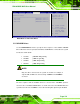


Table Of Contents
- 1 Introduction
- 2 Unpacking
- 3 Connectors
- 3.1 Peripheral Interface Connectors
- 3.2 Internal Peripheral Connectors
- 3.2.1 12V / 5V Power Connector
- 3.2.2 ATX Power Supply Enable Connector
- 3.2.3 Audio Kit Connector
- 3.2.4 Battery Connector
- 3.2.5 CompactFlash® Connector
- 3.2.6 Fan Connector
- 3.2.7 Digital I/O Connector
- 3.2.8 Keyboard/Mouse Connector
- 3.2.9 LAN Connector
- 3.2.10 LCD Inverter Connector
- 3.2.11 LED and +5V Output Connector
- 3.2.12 PCI-104 Connector
- 3.2.13 Power Button Connector
- 3.2.14 Reset Button Connector
- 3.2.15 RS-232 Serial Port Connectors
- 3.2.16 RS-422/485 Serial Port Connector
- 3.2.17 LVDS LCD Connector
- 3.2.18 SATA Drive Connector
- 3.2.19 SPI Flash Connector
- 3.2.20 USB Connector
- 3.2.21 VGA Connector
- 4 Installation
- 5 BIOS
- A BIOS Options
- B Terminology
- C Watchdog Timer
- D Hazardous Materials Disclosure
PM-945GSE-N270 User Manual
Page 107
1280 x 1024 36b
1400 x 1050 36b
1440 x 900 36b
1600 x 1200 36b
5.7.2 Southbridge Configuration
Use the Southbridge Configuration menu (BIOS Menu 21) to configure the audio
controller and spread spectrum function of the Southbridge chipset.
BIOS SETUP UTILITY
Main Advanced PCIPNP Boot Security Chipset Exit
Southbridge Configuration
Audio Controller [Auto]
Spread Spectrum Mode [Disabled]
Select Screen
Select Item
Enter Go to SubScreen
F1 General Help
F10 Save and Exit
ESC Exit
v02.61 ©Copyright 1985-2006, American Megatrends, Inc.
BIOS Menu 21:Southbridge Chipset Configuration
Audio Controller Codec [Auto]
Use the Audio Controller Codec option to enable or disable the audio controller codec.
All
Disabled
The audio controller codec is disabled
Auto DEFAULT
The audio controller codec is automatically detected and
enabled
Spread Spectrum [Disabled]
Use the Spread Spectrum option to reduce the EMI. Excess EMI is generated when the
system clock generator pulses have extreme values. Spreading the pulse spectrum