
Instruction Manual

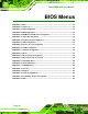


Table Of Contents
- 1 Introduction
- 2 Unpacking
- 3 Connectors
- 3.1 Peripheral Interface Connectors
- 3.2 Internal Peripheral Connectors
- 3.2.1 12V / 5V Power Connector
- 3.2.2 ATX Power Supply Enable Connector
- 3.2.3 Audio Kit Connector
- 3.2.4 Battery Connector
- 3.2.5 CompactFlash® Connector
- 3.2.6 Fan Connector
- 3.2.7 Digital I/O Connector
- 3.2.8 Keyboard/Mouse Connector
- 3.2.9 LAN Connector
- 3.2.10 LCD Inverter Connector
- 3.2.11 LED and +5V Output Connector
- 3.2.12 PCI-104 Connector
- 3.2.13 Power Button Connector
- 3.2.14 Reset Button Connector
- 3.2.15 RS-232 Serial Port Connectors
- 3.2.16 RS-422/485 Serial Port Connector
- 3.2.17 LVDS LCD Connector
- 3.2.18 SATA Drive Connector
- 3.2.19 SPI Flash Connector
- 3.2.20 USB Connector
- 3.2.21 VGA Connector
- 4 Installation
- 5 BIOS
- A BIOS Options
- B Terminology
- C Watchdog Timer
- D Hazardous Materials Disclosure
PM-945GSE-N270 User Manual
Page 17
Figure 1-3: PM-945GSE-N270 Motherboard Solder Side Overview
1.2.1 Connectors
The PM-945GSE-N270 motherboard has the following connectors on-board (described in
Chapter 3):
1 x AT/ATX 12V/5V connector
1 x CompactFlash® connector (solder side)
1 x Digital I/O connector
1 x Audio connector (supported via optional 5.1 channel audio kit with Realtek
ALC655 AC'97 codec or 7.1 channel HD audio kit with Realtek ALC883
codec)
1 x Keyboard/mouse connector
1 x LAN connector
1 x LCD Inverter connector