
Instruction Manual


Table Of Contents
- 1 Introduction
- 2 Unpacking
- 3 Connectors
- 3.1 Peripheral Interface Connectors
- 3.2 Internal Peripheral Connectors
- 3.2.1 12V / 5V Power Connector
- 3.2.2 ATX Power Supply Enable Connector
- 3.2.3 Audio Kit Connector
- 3.2.4 Battery Connector
- 3.2.5 CompactFlash® Connector
- 3.2.6 Fan Connector
- 3.2.7 Digital I/O Connector
- 3.2.8 Keyboard/Mouse Connector
- 3.2.9 LAN Connector
- 3.2.10 LCD Inverter Connector
- 3.2.11 LED and +5V Output Connector
- 3.2.12 PCI-104 Connector
- 3.2.13 Power Button Connector
- 3.2.14 Reset Button Connector
- 3.2.15 RS-232 Serial Port Connectors
- 3.2.16 RS-422/485 Serial Port Connector
- 3.2.17 LVDS LCD Connector
- 3.2.18 SATA Drive Connector
- 3.2.19 SPI Flash Connector
- 3.2.20 USB Connector
- 3.2.21 VGA Connector
- 4 Installation
- 5 BIOS
- A BIOS Options
- B Terminology
- C Watchdog Timer
- D Hazardous Materials Disclosure
PM-945GSE-N270 User Manual
Page 29
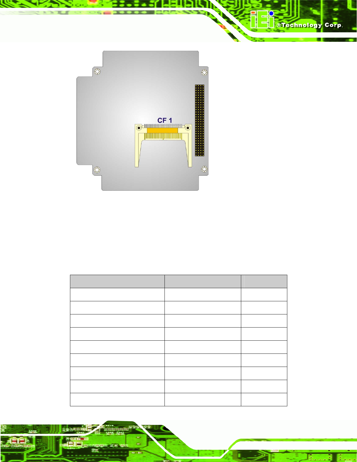
Figure 3-2: Connector and Jumper Locations (Solder Side)
3.1.2 Peripheral Interface Connectors
The table below shows a list of the peripheral interface connectors on the
PM-945GSE-N270 motherboard. Detailed descriptions of these connectors can be found
in the following section.
Connector Type Label
12V / 5V Power connector 3-pin terminal block CN3
ATX power control connector 3-pin wafer connector ATXCTL1
Audio connector 9-pin header CN7
Battery connector 2-pin wafer connector BAT1
CompactFlash® Type II connector 50-pin header CF1
CPU fan connector 3-pin header CPU_FAN1
Digital I/O connector 10-pin header CN5
Keyboard/Mouse connector 6-pin wafer connector KB_MS1
LAN connector 10-pin box header CN8