
Instruction Manual


Table Of Contents
- 1 Introduction
- 2 Unpacking
- 3 Connectors
- 3.1 Peripheral Interface Connectors
- 3.2 Internal Peripheral Connectors
- 3.2.1 12V / 5V Power Connector
- 3.2.2 ATX Power Supply Enable Connector
- 3.2.3 Audio Kit Connector
- 3.2.4 Battery Connector
- 3.2.5 CompactFlash® Connector
- 3.2.6 Fan Connector
- 3.2.7 Digital I/O Connector
- 3.2.8 Keyboard/Mouse Connector
- 3.2.9 LAN Connector
- 3.2.10 LCD Inverter Connector
- 3.2.11 LED and +5V Output Connector
- 3.2.12 PCI-104 Connector
- 3.2.13 Power Button Connector
- 3.2.14 Reset Button Connector
- 3.2.15 RS-232 Serial Port Connectors
- 3.2.16 RS-422/485 Serial Port Connector
- 3.2.17 LVDS LCD Connector
- 3.2.18 SATA Drive Connector
- 3.2.19 SPI Flash Connector
- 3.2.20 USB Connector
- 3.2.21 VGA Connector
- 4 Installation
- 5 BIOS
- A BIOS Options
- B Terminology
- C Watchdog Timer
- D Hazardous Materials Disclosure
PM-945GSE-N270 User Manual
Page 30
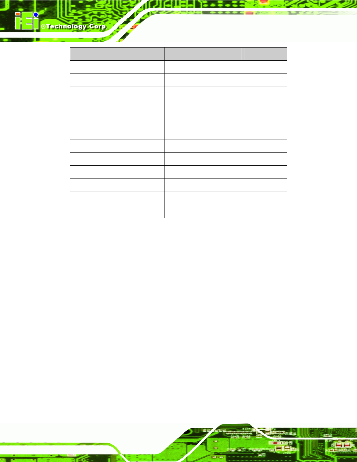
Connector Type Label
LCD inverter connector 5-pin wafer connector INVERTER1
LED and +5V output connector 6-pin wafer LED_C1
LVDS LCD connector 30-pin crimp connector LVDS1
PCI/104 connector 120-pin socket PC104_PLUS1
Power button connector 2-pin wafer PWRBTN1
Reset button connector 2-pin wafer RESET1
RS-232 Serial ports 1-4 connector 40-pin box header CN2
RS-422/85 Serial port connector 4-pin box header CN4
SATA drive connector 7-pin SATA drive connector CN1
SPI flash connector 6-pin wafer JSPI1
USB connectors 8-pin header CN9, CN10
VGA connector 10-pin header CN6
Table 3-1: Peripheral Interface Connectors
3.2 Internal Peripheral Connectors
Internal peripheral connectors on the motherboard are only accessible when the
motherboard is outside of the chassis. This section has complete descriptions of all the
internal, peripheral connectors on the PM-945GSE-N270 motherboard.
3.2.1 12V / 5V Power Connector
CN Label:
CN3
CN Type:
3-pin terminal block
CN Location:
See Figure 3-3
CN Pinou
ts:
See Table 3-2
The 12V / 5V Po
wer Connector supplies power to the motherboard.