
Instruction Manual


Table Of Contents
- 1 Introduction
- 2 Unpacking
- 3 Connectors
- 3.1 Peripheral Interface Connectors
- 3.2 Internal Peripheral Connectors
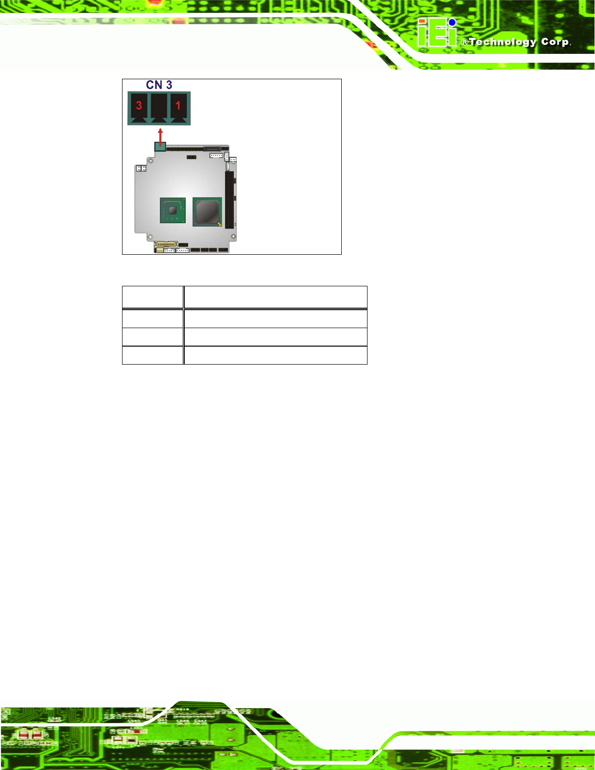
- 3.2.1 12V / 5V Power Connector
- 3.2.2 ATX Power Supply Enable Connector
- 3.2.3 Audio Kit Connector
- 3.2.4 Battery Connector
- 3.2.5 CompactFlash® Connector
- 3.2.6 Fan Connector
- 3.2.7 Digital I/O Connector
- 3.2.8 Keyboard/Mouse Connector
- 3.2.9 LAN Connector
- 3.2.10 LCD Inverter Connector
- 3.2.11 LED and +5V Output Connector
- 3.2.12 PCI-104 Connector
- 3.2.13 Power Button Connector
- 3.2.14 Reset Button Connector
- 3.2.15 RS-232 Serial Port Connectors
- 3.2.16 RS-422/485 Serial Port Connector
- 3.2.17 LVDS LCD Connector
- 3.2.18 SATA Drive Connector
- 3.2.19 SPI Flash Connector
- 3.2.20 USB Connector
- 3.2.21 VGA Connector
- 4 Installation
- 5 BIOS
- A BIOS Options
- B Terminology
- C Watchdog Timer
- D Hazardous Materials Disclosure
PM-945GSE-N270 User Manual
Page 31
Figure 3-3: 12V / 5V Power Connector Location
PIN NO. DESCRIPTION
1 VCC12
2 GND
3 VCC5
Table 3-2: 12V / 5V Power Connector Pinouts
3.2.2 ATX Power Supply Enable Connector
CN Label: ATXCTL1
CN Type:
3-pin wafer (1x3)
CN Location:
See Figure 3-4
CN Pinou
ts:
See Table 3-3
The co
nnector is for enabling an ATX power supply. When connected to the power supply,
the power can be turned on and off with the front panel switch. Use the optional ATX
power cable. Pins 2-3 are shorted by default for AT power.