
Instruction Manual


Table Of Contents
- 1 Introduction
- 2 Unpacking
- 3 Connectors
- 3.1 Peripheral Interface Connectors
- 3.2 Internal Peripheral Connectors
- 3.2.1 12V / 5V Power Connector
- 3.2.2 ATX Power Supply Enable Connector
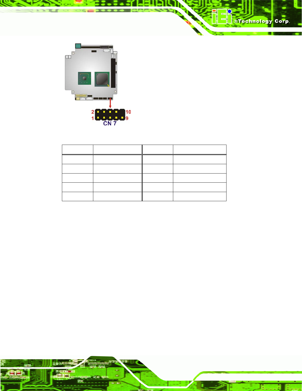
- 3.2.3 Audio Kit Connector
- 3.2.4 Battery Connector
- 3.2.5 CompactFlash® Connector
- 3.2.6 Fan Connector
- 3.2.7 Digital I/O Connector
- 3.2.8 Keyboard/Mouse Connector
- 3.2.9 LAN Connector
- 3.2.10 LCD Inverter Connector
- 3.2.11 LED and +5V Output Connector
- 3.2.12 PCI-104 Connector
- 3.2.13 Power Button Connector
- 3.2.14 Reset Button Connector
- 3.2.15 RS-232 Serial Port Connectors
- 3.2.16 RS-422/485 Serial Port Connector
- 3.2.17 LVDS LCD Connector
- 3.2.18 SATA Drive Connector
- 3.2.19 SPI Flash Connector
- 3.2.20 USB Connector
- 3.2.21 VGA Connector
- 4 Installation
- 5 BIOS
- A BIOS Options
- B Terminology
- C Watchdog Timer
- D Hazardous Materials Disclosure
PM-945GSE-N270 User Manual
Page 33
Figure 3-5: Audio Kit Connector Location
Pin Description Pin Description
1 SYNC 2 BITCLK
3 SDOUT 4 PCBEEP
5 SDIN 6 RST#
7 VCC 8 GND
9 +12 V
Table 3-4: Audio Kit Connector Pinouts
3.2.4 Battery Connector
CN Label: BAT1
CN Type:
2-pin wafer connector
CN Location:
See Figure 3-6
CN Pinou
ts:
See Table 3-5
This battery
connector connects to an externally mounted 3V, Lithium, cell coin battery
(VARTA CR2032). The life expectancy of the battery is approximately seven years.
Depending on the working condition, the life expectancy may be shorter.
Replacing the battery is not a user operation.
If the battery starts to weaken and lose voltage, contact a vendor or IEI for a replacement
module. Dispose of the used battery properly. Contact the local waste disposal agency for