
Instruction Manual


Table Of Contents
- 1 Introduction
- 2 Unpacking
- 3 Connectors
- 3.1 Peripheral Interface Connectors
- 3.2 Internal Peripheral Connectors
- 3.2.1 12V / 5V Power Connector
- 3.2.2 ATX Power Supply Enable Connector
- 3.2.3 Audio Kit Connector
- 3.2.4 Battery Connector
- 3.2.5 CompactFlash® Connector
- 3.2.6 Fan Connector
- 3.2.7 Digital I/O Connector
- 3.2.8 Keyboard/Mouse Connector
- 3.2.9 LAN Connector
- 3.2.10 LCD Inverter Connector
- 3.2.11 LED and +5V Output Connector
- 3.2.12 PCI-104 Connector
- 3.2.13 Power Button Connector
- 3.2.14 Reset Button Connector
- 3.2.15 RS-232 Serial Port Connectors
- 3.2.16 RS-422/485 Serial Port Connector
- 3.2.17 LVDS LCD Connector
- 3.2.18 SATA Drive Connector
- 3.2.19 SPI Flash Connector
- 3.2.20 USB Connector
- 3.2.21 VGA Connector
- 4 Installation
- 5 BIOS
- A BIOS Options
- B Terminology
- C Watchdog Timer
- D Hazardous Materials Disclosure
PM-945GSE-N270 User Manual
Page 34
disposal instructions. Do not dispose of a used battery with normal household waste.
WARNING!
1. Keep batteries away from children.
2. There is a danger of explosion if the battery is incorrectly replaced.
3. Only a certified module from IEI can be used as a replacement.
4. Do not expose the battery to excessive heat or fire.
5. If the battery shows signs of leakage, contact a local vendor or IEI immediately.
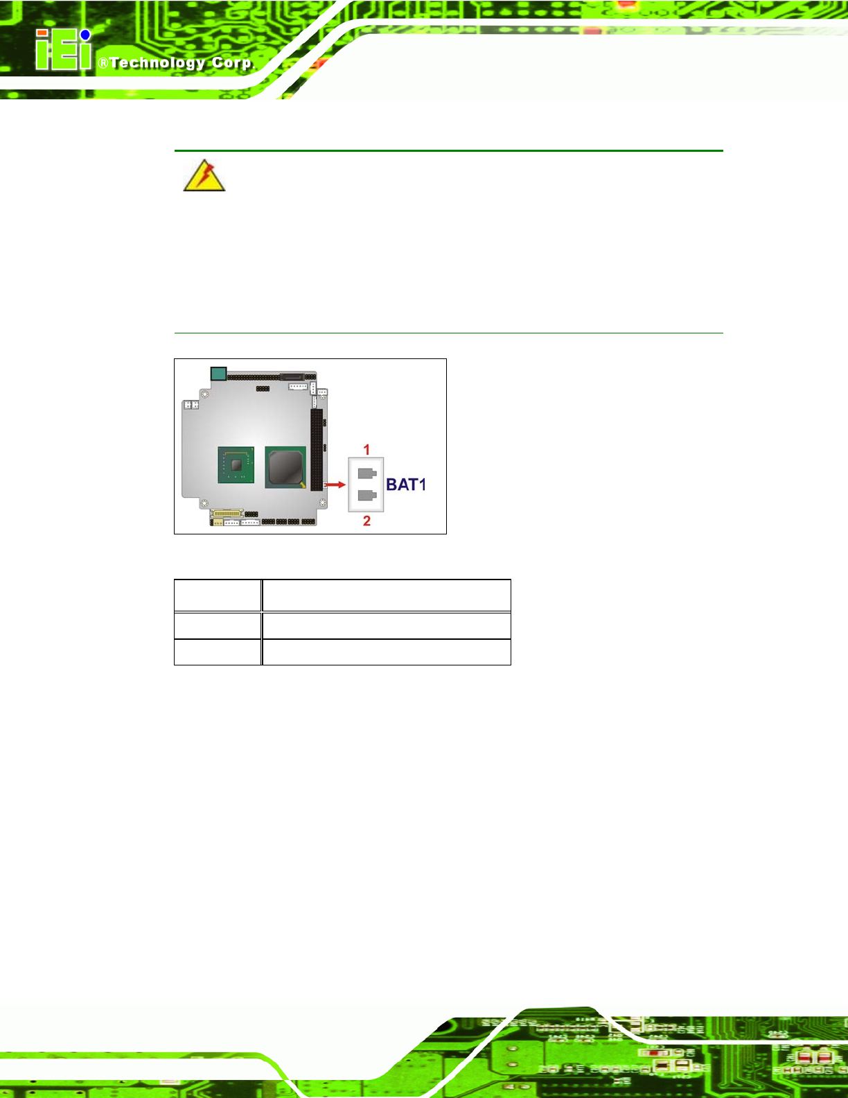
Figure 3-6: Battery Connector Location
PIN NO. DESCRIPTION
1 BAT+
2 GND
Table 3-5: Battery Connector Pinouts
3.2.5 CompactFlash® Connector
CN Label:
CF1 (solder side)
CN Type:
50-pin header (2x25)
CN Location:
See Figure 3-7
CN Pinou
ts:
See Table 3-6
A Compa
ctFlash® memory module is inserted to the CompactFlash® connector.