
Instruction Manual


Table Of Contents
- 1 Introduction
- 2 Unpacking
- 3 Connectors
- 3.1 Peripheral Interface Connectors
- 3.2 Internal Peripheral Connectors
- 3.2.1 12V / 5V Power Connector
- 3.2.2 ATX Power Supply Enable Connector
- 3.2.3 Audio Kit Connector
- 3.2.4 Battery Connector
- 3.2.5 CompactFlash® Connector
- 3.2.6 Fan Connector
- 3.2.7 Digital I/O Connector
- 3.2.8 Keyboard/Mouse Connector
- 3.2.9 LAN Connector
- 3.2.10 LCD Inverter Connector
- 3.2.11 LED and +5V Output Connector
- 3.2.12 PCI-104 Connector
- 3.2.13 Power Button Connector
- 3.2.14 Reset Button Connector
- 3.2.15 RS-232 Serial Port Connectors
- 3.2.16 RS-422/485 Serial Port Connector
- 3.2.17 LVDS LCD Connector
- 3.2.18 SATA Drive Connector
- 3.2.19 SPI Flash Connector
- 3.2.20 USB Connector
- 3.2.21 VGA Connector
- 4 Installation
- 5 BIOS
- A BIOS Options
- B Terminology
- C Watchdog Timer
- D Hazardous Materials Disclosure
PM-945GSE-N270 User Manual
Page 35
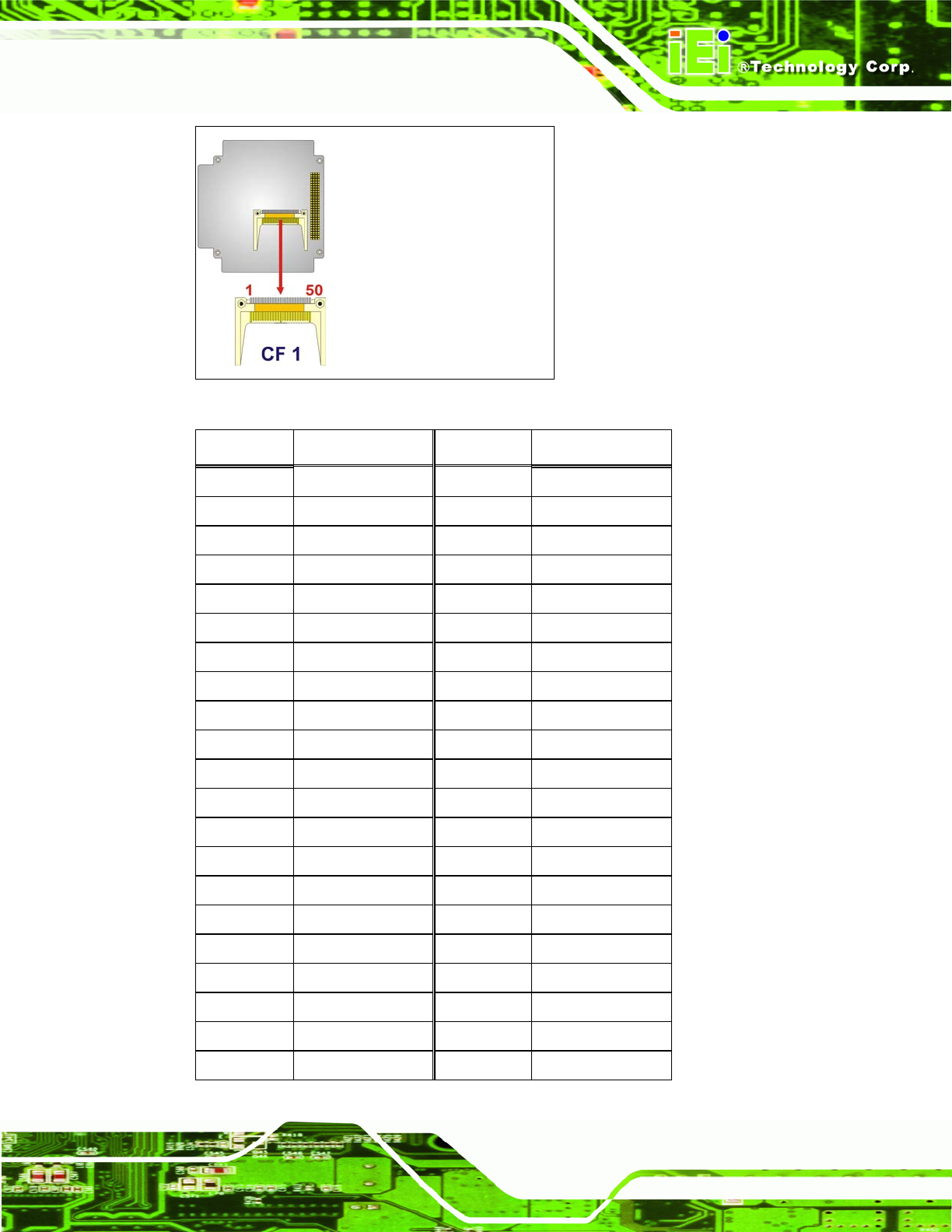
Figure 3-7: CompactFlash® Connector Location
PIN NO. DESCRIPTION PIN NO. DESCRIPTION
1 GND 2 D3
3 D4 4 D5
5 D6 6 D7
7 CE# 8 GND
9 GND 10 GND
11 GND 12 GND
13 VCC (+5V) 14 GND
15 GND 16 GND
17 GND 18 A2
19 A1 20 A0
21 D0 22 D1
23 D2 24 NC
25 CD2# 26 CD1#
27 D11 28 D12
29 D13 30 D14
31 D15 32 CE2#
33 NC 34 IOR#
35 IOW# 36 WE#
37 IRQ 38 VCC(+5V)
39 CSEL# 40 NC
41 RESET# 42 WAIT#