
Instruction Manual


Table Of Contents
- 1 Introduction
- 2 Unpacking
- 3 Connectors
- 3.1 Peripheral Interface Connectors
- 3.2 Internal Peripheral Connectors
- 3.2.1 12V / 5V Power Connector
- 3.2.2 ATX Power Supply Enable Connector
- 3.2.3 Audio Kit Connector
- 3.2.4 Battery Connector
- 3.2.5 CompactFlash® Connector
- 3.2.6 Fan Connector
- 3.2.7 Digital I/O Connector
- 3.2.8 Keyboard/Mouse Connector
- 3.2.9 LAN Connector
- 3.2.10 LCD Inverter Connector
- 3.2.11 LED and +5V Output Connector
- 3.2.12 PCI-104 Connector
- 3.2.13 Power Button Connector
- 3.2.14 Reset Button Connector
- 3.2.15 RS-232 Serial Port Connectors
- 3.2.16 RS-422/485 Serial Port Connector
- 3.2.17 LVDS LCD Connector
- 3.2.18 SATA Drive Connector
- 3.2.19 SPI Flash Connector
- 3.2.20 USB Connector
- 3.2.21 VGA Connector
- 4 Installation
- 5 BIOS
- A BIOS Options
- B Terminology
- C Watchdog Timer
- D Hazardous Materials Disclosure
PM-945GSE-N270 User Manual
Page 39
The PM-945GSE-N270 is equipped with an Ethernet controller. The Ethernet controller is
interfaced to the external LAN by direct connection to the LAN connection or by
connecting the LAN connector to an RJ-45 interface connector.
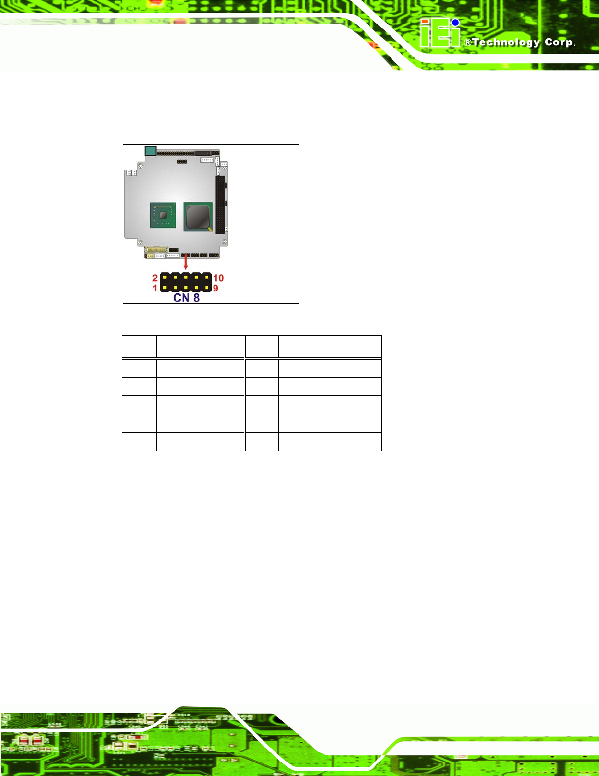
Figure 3-11: LAN Connector Location
PIN DESCRIPTION PIN DESCRIPTION
1 VCC3.3 6 Active
2 RX+ 7 RX-
3 Link 8 GND
4 N/C 9 GND
5 TX+ 10 TX-
Table 3-10: LAN Connector Pinouts
3.2.10 LCD Inverter Connector
CN Label:
INVERTER1
CN Type:
5-pin wafer connector
CN Location:
See Figure 3-12
CN Pinou
ts:
See Table 3-11
The Inverte
r connector connects to the LCD backlight.