
Instruction Manual


Table Of Contents
- 1 Introduction
- 2 Unpacking
- 3 Connectors
- 3.1 Peripheral Interface Connectors
- 3.2 Internal Peripheral Connectors
- 3.2.1 12V / 5V Power Connector
- 3.2.2 ATX Power Supply Enable Connector
- 3.2.3 Audio Kit Connector
- 3.2.4 Battery Connector
- 3.2.5 CompactFlash® Connector
- 3.2.6 Fan Connector
- 3.2.7 Digital I/O Connector
- 3.2.8 Keyboard/Mouse Connector
- 3.2.9 LAN Connector
- 3.2.10 LCD Inverter Connector
- 3.2.11 LED and +5V Output Connector
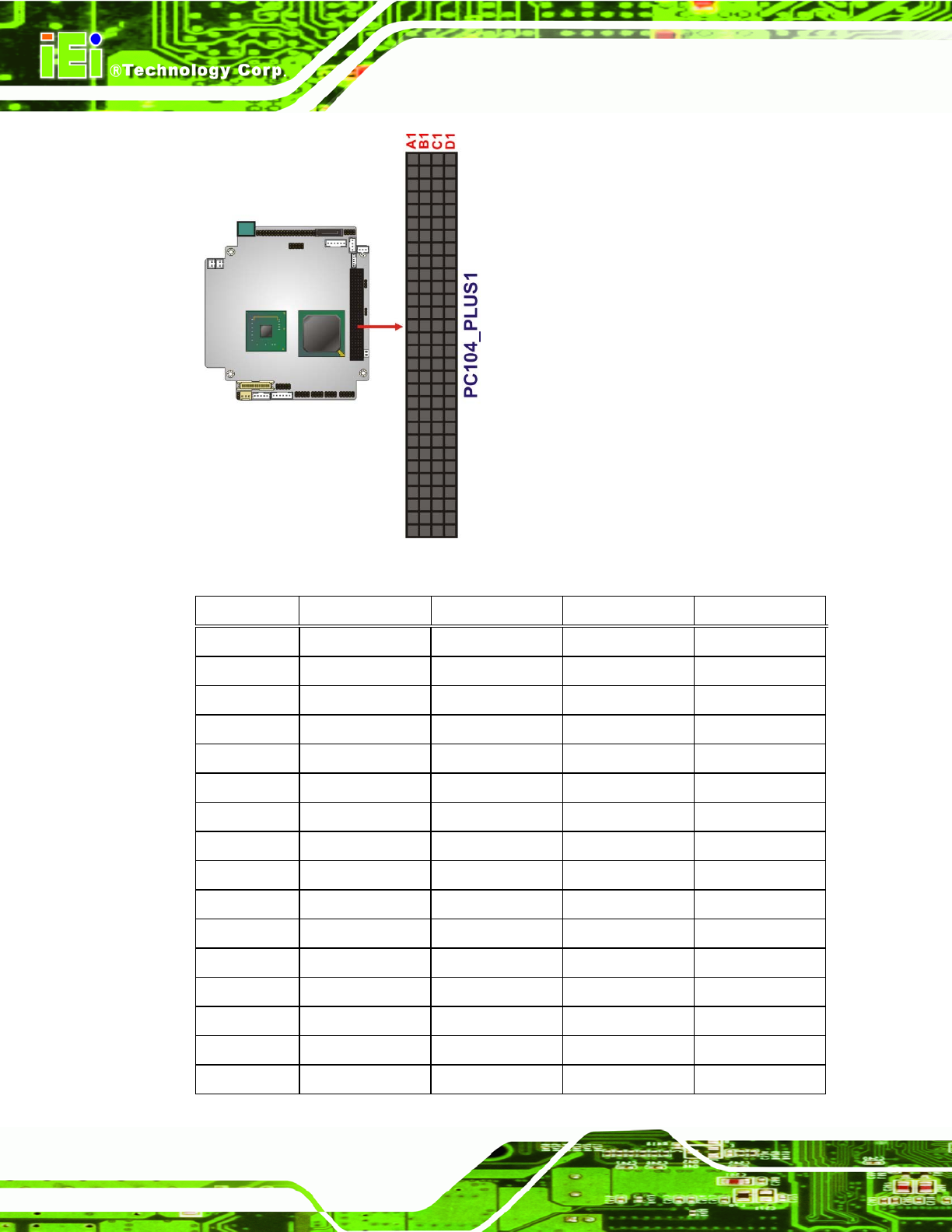
- 3.2.12 PCI-104 Connector
- 3.2.13 Power Button Connector
- 3.2.14 Reset Button Connector
- 3.2.15 RS-232 Serial Port Connectors
- 3.2.16 RS-422/485 Serial Port Connector
- 3.2.17 LVDS LCD Connector
- 3.2.18 SATA Drive Connector
- 3.2.19 SPI Flash Connector
- 3.2.20 USB Connector
- 3.2.21 VGA Connector
- 4 Installation
- 5 BIOS
- A BIOS Options
- B Terminology
- C Watchdog Timer
- D Hazardous Materials Disclosure
PM-945GSE-N270 User Manual
Page 42
Figure 3-14: PCI-104 Connector Location
Pin No. Column A Column B Column C Column D
1 GND/5 V TBD1 5 V AD00
2 VI/O1 AD02 AD01 +5 V
3 AD05 GND AD04 AD03
4 C/BE0# AD07 GND AD06
5 GND AD09 AD08 GND
6 AD11 VI/O2 AD10 M66EN
7 AD14 AD13 GND AD12
8 +3.3 V C/BE1# AD15 +3.3 V
9 SERR# GND SB0# PAR
10 GND PERR# +3.3 V SDONE
11 STOP# +3.3 V LOCK# GND
12 +3.3 V TRDY# GND DEVSEL#
13 FRAME# GND IRDY# +3.3 V
14 GND AD16 +3.3 V C/BE2#
15 AD18 +3.3 V AD17 GND
16 AD21 AD20 GND AD19