
Instruction Manual


Table Of Contents
- 1 Introduction
- 2 Unpacking
- 3 Connectors
- 3.1 Peripheral Interface Connectors
- 3.2 Internal Peripheral Connectors
- 3.2.1 12V / 5V Power Connector
- 3.2.2 ATX Power Supply Enable Connector
- 3.2.3 Audio Kit Connector
- 3.2.4 Battery Connector
- 3.2.5 CompactFlash® Connector
- 3.2.6 Fan Connector
- 3.2.7 Digital I/O Connector
- 3.2.8 Keyboard/Mouse Connector
- 3.2.9 LAN Connector
- 3.2.10 LCD Inverter Connector
- 3.2.11 LED and +5V Output Connector
- 3.2.12 PCI-104 Connector
- 3.2.13 Power Button Connector
- 3.2.14 Reset Button Connector
- 3.2.15 RS-232 Serial Port Connectors
- 3.2.16 RS-422/485 Serial Port Connector
- 3.2.17 LVDS LCD Connector
- 3.2.18 SATA Drive Connector
- 3.2.19 SPI Flash Connector
- 3.2.20 USB Connector
- 3.2.21 VGA Connector
- 4 Installation
- 5 BIOS
- A BIOS Options
- B Terminology
- C Watchdog Timer
- D Hazardous Materials Disclosure
PM-945GSE-N270 User Manual
Page 46
15 TX2 16 CTS2#
17 DTR2# 18 RI2#
19 GND 20 GND
21 DCD3# 22 DSR3#
23 RX3 24 RTS3#
25 TX3 26 CTS3#
27 DTR3# 28 RI3#
29 GND 30 GND
31 DCD4# 32 DSR4#
33 RX4 34 RTS4#
35 TX4 36 CTS4#
37 DTR4# 38 RI4#
39 GND 40 GND
Table 3-16: RS-232 Serial Port Connector Pinouts
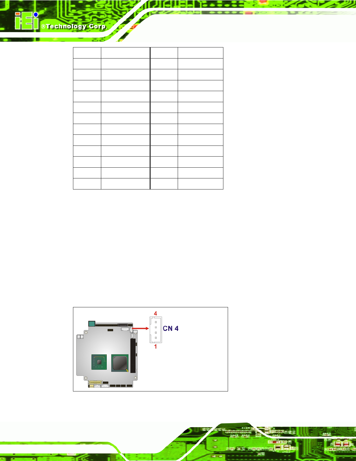
3.2.16 RS-422/485 Serial Port Connector
CN Label:
CN4
CN Type:
4-pin wafer connector
CN Location:
See Figure 3-18
CN Pinou
ts:
See Table 3-17
The se
rial port connector connects to an RS-422 or RS-485 serial port device.
Figure 3-18: RS-422/485 Serial Port Connector Location