
Instruction Manual


Table Of Contents
- 1 Introduction
- 2 Unpacking
- 3 Connectors
- 3.1 Peripheral Interface Connectors
- 3.2 Internal Peripheral Connectors
- 3.2.1 12V / 5V Power Connector
- 3.2.2 ATX Power Supply Enable Connector
- 3.2.3 Audio Kit Connector
- 3.2.4 Battery Connector
- 3.2.5 CompactFlash® Connector
- 3.2.6 Fan Connector
- 3.2.7 Digital I/O Connector
- 3.2.8 Keyboard/Mouse Connector
- 3.2.9 LAN Connector
- 3.2.10 LCD Inverter Connector
- 3.2.11 LED and +5V Output Connector
- 3.2.12 PCI-104 Connector
- 3.2.13 Power Button Connector
- 3.2.14 Reset Button Connector
- 3.2.15 RS-232 Serial Port Connectors
- 3.2.16 RS-422/485 Serial Port Connector
- 3.2.17 LVDS LCD Connector
- 3.2.18 SATA Drive Connector
- 3.2.19 SPI Flash Connector
- 3.2.20 USB Connector
- 3.2.21 VGA Connector
- 4 Installation
- 5 BIOS
- A BIOS Options
- B Terminology
- C Watchdog Timer
- D Hazardous Materials Disclosure
PM-945GSE-N270 User Manual
Page 57
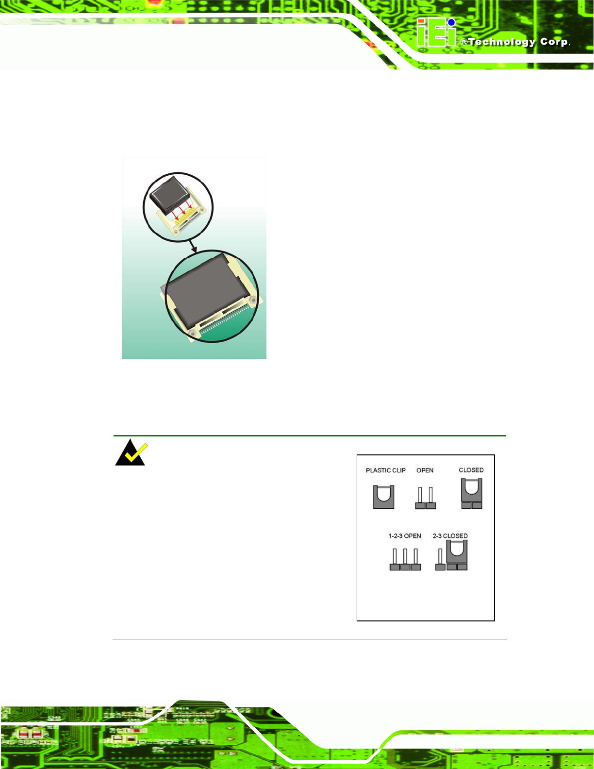
Step 1: Turn the CPU board over so that the CF Type II card socket is facing up.
Step 2: Gently push the CF Type II card into the socket until it clicks into place. (See
Figure 4-1)
Figure 4-1: CompactFlash® Card Installation
4.5 Jumper Settings
NOTE:
A
jumper is a metal bridge that is used to
close an electrical circuit. It consists of two
metal pins and a small metal clip (protected by
a plastic cover) that slides over the pins to
connect them. To CLOSE/SHORT a jumper
means connecting the pins of the jumper with
the plastic clip and to OPEN a jumper means
removing the plastic clip from a jumper.
Jumper