
Instruction Manual


Table Of Contents
- 1 Introduction
- 2 Unpacking
- 3 Connectors
- 3.1 Peripheral Interface Connectors
- 3.2 Internal Peripheral Connectors
- 3.2.1 12V / 5V Power Connector
- 3.2.2 ATX Power Supply Enable Connector
- 3.2.3 Audio Kit Connector
- 3.2.4 Battery Connector
- 3.2.5 CompactFlash® Connector
- 3.2.6 Fan Connector
- 3.2.7 Digital I/O Connector
- 3.2.8 Keyboard/Mouse Connector
- 3.2.9 LAN Connector
- 3.2.10 LCD Inverter Connector
- 3.2.11 LED and +5V Output Connector
- 3.2.12 PCI-104 Connector
- 3.2.13 Power Button Connector
- 3.2.14 Reset Button Connector
- 3.2.15 RS-232 Serial Port Connectors
- 3.2.16 RS-422/485 Serial Port Connector
- 3.2.17 LVDS LCD Connector
- 3.2.18 SATA Drive Connector
- 3.2.19 SPI Flash Connector
- 3.2.20 USB Connector
- 3.2.21 VGA Connector
- 4 Installation
- 5 BIOS
- A BIOS Options
- B Terminology
- C Watchdog Timer
- D Hazardous Materials Disclosure
PM-945GSE-N270 User Manual
Page 58
Before the PM-945GSE-N270 is installed in the system, the jumpers must be set in
accordance with the desired configuration. There are three jumpers on the
PM-945GSE-N270. These three jumpers are listed in the table below.
Description Label Type
Clear CMOS J_CMOS1 3-pin header
COM3 RS-232/422/485 select JP1 8-pin header
LCD voltage select J_LVDS1 3-pin header
PCI-104 I/O voltage select JP2 3-pin header
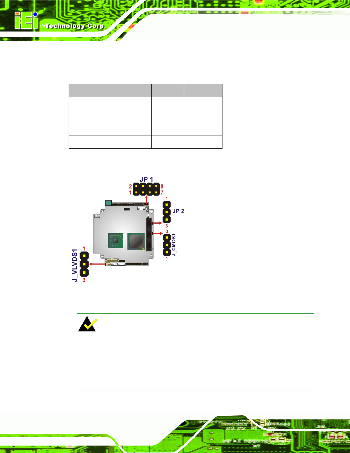
The PM-945GSE-N270 CPU board has four onboard jumpers (Figure 4-2).
Figure 4-2: Jumper Locations
NOTE:
The PM-945GSE-N270 does not provide a “Clear CMOS” configuration jumper. If the
system fails to boot due to improper BIOS settings, reset the CMOS contents by
disconnecting and reconnecting the BT1 battery connector. Use small-sized needle
nose pliers to carefully disconnect and reconnect the BT1 battery connector.