
Instruction Manual


Table Of Contents
- 1 Introduction
- 2 Unpacking
- 3 Connectors
- 3.1 Peripheral Interface Connectors
- 3.2 Internal Peripheral Connectors
- 3.2.1 12V / 5V Power Connector
- 3.2.2 ATX Power Supply Enable Connector
- 3.2.3 Audio Kit Connector
- 3.2.4 Battery Connector
- 3.2.5 CompactFlash® Connector
- 3.2.6 Fan Connector
- 3.2.7 Digital I/O Connector
- 3.2.8 Keyboard/Mouse Connector
- 3.2.9 LAN Connector
- 3.2.10 LCD Inverter Connector
- 3.2.11 LED and +5V Output Connector
- 3.2.12 PCI-104 Connector
- 3.2.13 Power Button Connector
- 3.2.14 Reset Button Connector
- 3.2.15 RS-232 Serial Port Connectors
- 3.2.16 RS-422/485 Serial Port Connector
- 3.2.17 LVDS LCD Connector
- 3.2.18 SATA Drive Connector
- 3.2.19 SPI Flash Connector
- 3.2.20 USB Connector
- 3.2.21 VGA Connector
- 4 Installation
- 5 BIOS
- A BIOS Options
- B Terminology
- C Watchdog Timer
- D Hazardous Materials Disclosure
PM-945GSE-N270 User Manual
Page 65
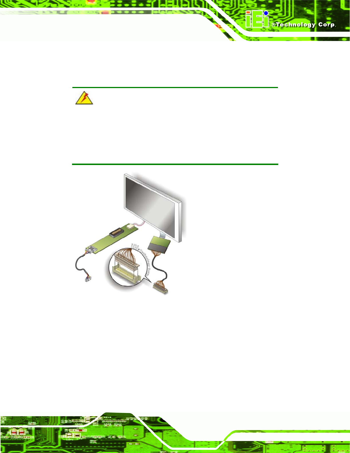
Step 2: Insert the cable connector. Insert the connector from the LVDS PCB driving
board to the LVDS connector as shown in Figure 4-8. When
connecting the
connectors, make sure the pins are properly aligned.
WARNING:
The diagram below is merely for illustration. The configuration and
connection of the cables from the TFT LCD screen being installed may
be different. Please refer to the installation manual that came with the
TFT LCD screen.
Figure 4-8: LVDS Connector
Step 3: Locate the backlight inverter connector. The location of the backlight inverter
connector is shown in Chapter 3.
Step 4: Connect backlight connector. Connect the backlight connector to the driver
TFT LCD PCB as shown in Figure 4-9. When in
serting the cable connector,
make sure the pins are properly aligned. Step 0: