
Instruction Manual


Table Of Contents
- 1 Introduction
- 2 Unpacking
- 3 Connectors
- 3.1 Peripheral Interface Connectors
- 3.2 Internal Peripheral Connectors
- 3.2.1 12V / 5V Power Connector
- 3.2.2 ATX Power Supply Enable Connector
- 3.2.3 Audio Kit Connector
- 3.2.4 Battery Connector
- 3.2.5 CompactFlash® Connector
- 3.2.6 Fan Connector
- 3.2.7 Digital I/O Connector
- 3.2.8 Keyboard/Mouse Connector
- 3.2.9 LAN Connector
- 3.2.10 LCD Inverter Connector
- 3.2.11 LED and +5V Output Connector
- 3.2.12 PCI-104 Connector
- 3.2.13 Power Button Connector
- 3.2.14 Reset Button Connector
- 3.2.15 RS-232 Serial Port Connectors
- 3.2.16 RS-422/485 Serial Port Connector
- 3.2.17 LVDS LCD Connector
- 3.2.18 SATA Drive Connector
- 3.2.19 SPI Flash Connector
- 3.2.20 USB Connector
- 3.2.21 VGA Connector
- 4 Installation
- 5 BIOS
- A BIOS Options
- B Terminology
- C Watchdog Timer
- D Hazardous Materials Disclosure
PM-945GSE-N270 User Manual
Page 91
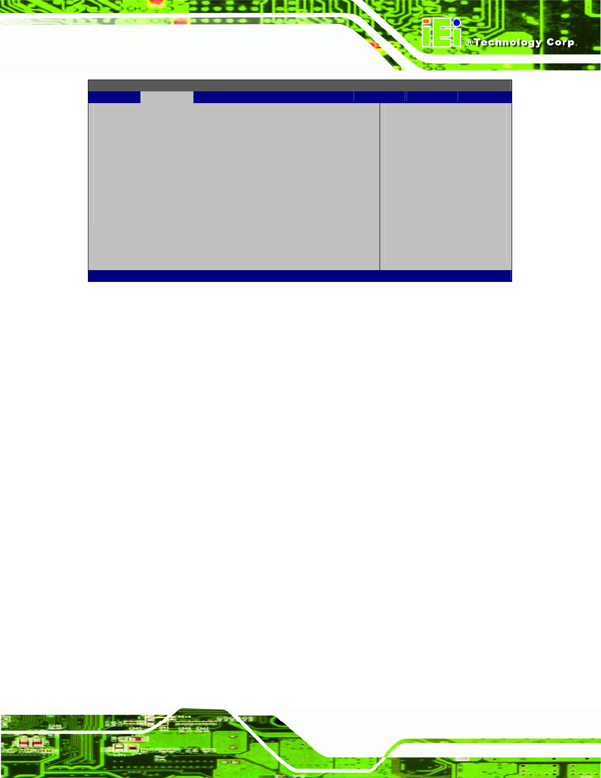
BIOS SETUP UTILITY
Main Advanced PCIPNP Boot Security Chipset Exit
Configure Remote Access type and parameters
Remote Access [Disabled]
Serial port number [COM1]
Base Address, IRQ [3F8H, 3]
Serial Port Mode [115200 8,n,1]
Redirection After BIOS POST [Always]
Terminal Type [ANSI]
Select Screen
Select Item
Enter Go to SubScreen
F1 General Help
F10 Save and Exit
ESC Exit
v02.61 ©Copyright 1985-2006, American Megatrends, Inc.
BIOS Menu 9: Remote Access Configuration
Remote Access [Disabled]
Use the Remote Access option to enable or disable access to the remote functionalities
of the system.
Disabled DEFAULT
Remote access is disabled.
Enabled
Remote access configuration options shown below
appear:
Serial Port Number
Serial Port Mode
Flow Control
Redirection after BIOS POST
Terminal Type
VT-UTF8 Combo Key Support
These configuration options are discussed below.
Serial Port r [1]
Use the Detected Serial Port option to select the serial port used for remote access.