
Instruction Manual


Table Of Contents
- 1 Introduction
- 2 Unpacking
- 3 Connectors
- 3.1 Peripheral Interface Connectors
- 3.2 Internal Peripheral Connectors
- 3.2.1 12V / 5V Power Connector
- 3.2.2 ATX Power Supply Enable Connector
- 3.2.3 Audio Kit Connector
- 3.2.4 Battery Connector
- 3.2.5 CompactFlash® Connector
- 3.2.6 Fan Connector
- 3.2.7 Digital I/O Connector
- 3.2.8 Keyboard/Mouse Connector
- 3.2.9 LAN Connector
- 3.2.10 LCD Inverter Connector
- 3.2.11 LED and +5V Output Connector
- 3.2.12 PCI-104 Connector
- 3.2.13 Power Button Connector
- 3.2.14 Reset Button Connector
- 3.2.15 RS-232 Serial Port Connectors
- 3.2.16 RS-422/485 Serial Port Connector
- 3.2.17 LVDS LCD Connector
- 3.2.18 SATA Drive Connector
- 3.2.19 SPI Flash Connector
- 3.2.20 USB Connector
- 3.2.21 VGA Connector
- 4 Installation
- 5 BIOS
- A BIOS Options
- B Terminology
- C Watchdog Timer
- D Hazardous Materials Disclosure
PM-945GSE-N270 User Manual
Page 93
Disabled
The console is not redirected after POST
Boot Loader
Redirection is active during POST and during Boot
Loader
Always DEFAULT
Redirection is always active (Some OSes may not
work if set to Always)
Terminal Type [ANSI]
Use the Terminal Type BIOS option to specify the remote terminal type.
ANSI DEFAULT
The target terminal type is ANSI
VT100
The target terminal type is VT100
VT-UTF8
The target terminal type is VT-UTF8
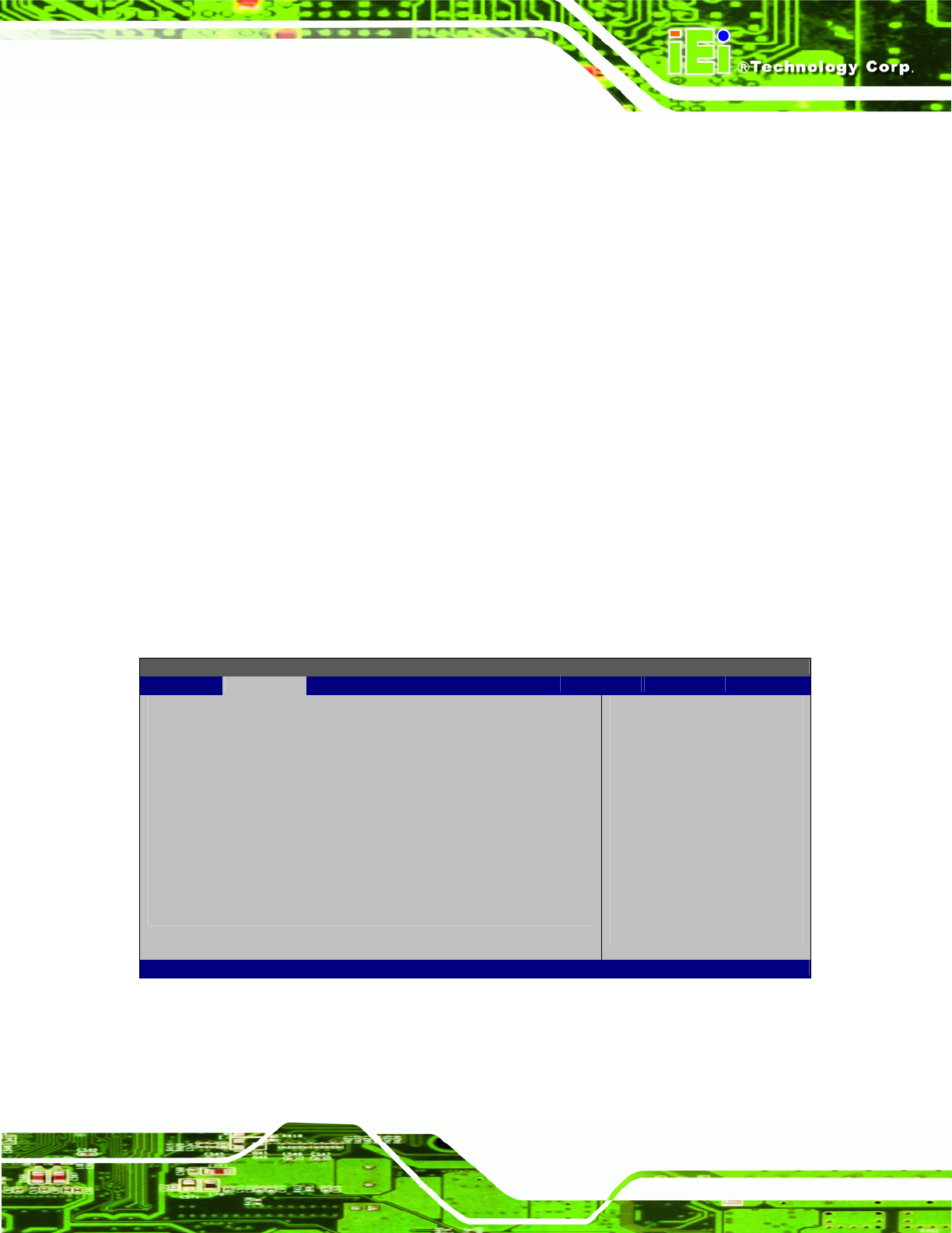
5.3.7 USB Configuration
Use the USB Configuration menu (BIOS Menu 10) to read USB configuration
information and configure the USB settings.
BIOS SETUP UTILITY
Main Advanced PCIPNP Boot Security Chipset Exit
USB Configuration
Module Version – 2.24.3-13.4
USB Devices Enabled:
None
USB Function [Enabled]
Legacy USB Support [Enabled]
USB 2.0 Controller [Enabled]
USB 2.0 Controller Mode [HiSpeed]
Enables USB host
controllers
Select Screen
Select Item
Enter Go to SubScreen
F1 General Help
F10 Save and Exit
ESC Exit
v02.61 ©Copyright 1985-2006, American Megatrends, Inc.
BIOS Menu 10: USB Configuration