PM-P006UPS DC/DC Converter Module PM-P006UPS DC/DC Converter Module Page i
PM-P006UPS DC/DC Converter Module Revision Date Version Changes 2007-11 1.
PM-P006UPS DC/DC Converter Module Copyright COPYRIGHT NOTICE The information in this document is subject to change without prior notice in order to improve reliability, design and function and does not represent a commitment on the part of the manufacturer. In no event will the manufacturer be liable for direct, indirect, special, incidental, or consequential damages arising out of the use or inability to use the product or documentation, even if advised of the possibility of such damages.
PM-P006UPS DC/DC Converter Module Packing List NOTE: If any of the components listed in the checklist below are missing, please do not proceed with the installation. Contact the IEI reseller or vendor you purchased the PM-P006UPS from or contact an IEI sales representative directly. To contact an IEI sales representative, please send an email to sales@iei.com.tw. 0H The items listed below should all be included in the PM-P006UPS package.
PM-P006UPS DC/DC Converter Module Table of Contents 1 INTRODUCTION..................................................................................................... 1 1H 82H 1.1 PM-P006UPS OVERVIEW .......................................................................................... 2 1.2 PM-P006UPS POWER MODULE FEATURES ............................................................... 2 1.3 PM-P006UPS DIMENSIONS ....................................................................................
PM-P006UPS DC/DC Converter Module 5.2.1 Using the Application....................................................................................... 26 5.2.2 Status Information............................................................................................ 28 5.2.2.1 DC Detection ............................................................................................ 29 5.2.2.2 Battery Detection ...................................................................................... 29 5.2.2.
PM-P006UPS DC/DC Converter Module List of Figures Figure 1-1: PM-P006UPS DC/DC Converter Module ..................................................2 41H 12H Figure 1-2: Output Power and Temperature...............................................................3 42H 123H Figure 1-3: PM-P006UPS Dimensions (mm) ...............................................................4 43H 124H Figure 2-1: PM-P006UPS System Block Diagram ......................................................
PM-P006UPS DC/DC Converter Module List of Tables Table 1-1: Output Voltage.............................................................................................3 68H 149H Table 2-1: BAT-LI-2S1P3000 Specifications ...............................................................8 69H 150H Table 3-1: Package List Contents..............................................................................11 70H 15H Table 3-2: Optional Items ................................................................
PM-P006UPS DC/DC Converter Module Chapter 1 1 Introduction Page 1
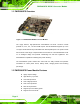
PM-P006UPS DC/DC Converter Module 1.1 PM-P006UPS Overview Figure 1-1: PM-P006UPS DC/DC Converter Module The highly efficient, high-performance PM-P006UPS DC-to-DC converter module provides 5V, 3.3V, 12V, -12V and 5VSB outputs. The PM-P006UPS supports up to two Li-Polymer smart batteries to provide stable and uninterruptible power. The power module also receives a wide range of inputs between 6V and 36V DC.
PM-P006UPS DC/DC Converter Module RoHS compliant I/O interface: o o SMBus/I2C RS-232 Utility software: pull data out through RS-232 to system Total output capacity: 65W Input Voltage: 6V to 36V DC Output Voltage: Voltage +5V +12V -12V +3.3V 5VSB Max. Load 10A 4A 0.
PM-P006UPS DC/DC Converter Module 1.3 PM-P006UPS Dimensions Figure 1-3 shows the PM-P006UPS dimensions. The dimensions are given in millimeters.
PM-P006UPS DC/DC Converter Module Chapter 2 2 Detailed Specifications Page 5
PM-P006UPS DC/DC Converter Module 2.1 PM-P006UPS System Block Diagram Figure 2-1 shows the system block diagram of the PM-P006UPS. The detailed 154H62 descriptions of the system operation are described in the following sections. Figure 2-1: PM-P006UPS System Block Diagram The PM-P006UPS is a charging circuit that provides the Smart Battery with charging current and charging voltage from DC input to match the requirements from Smart Battery.
PM-P006UPS DC/DC Converter Module communication channel) The Host System (SMBus Host) requests information from the battery and then uses it to provide the user information about the battery present state and capabilities. The Host System (SMBus Host) also receives critical events from the Smart Battery when it detects a problem. Using the utility software, the battery state and capabilities can be shown in the Host System through RS-232. 2.
PM-P006UPS DC/DC Converter Module 2.3 Battery Specifications The PM-P006UPS may also come with a Li-Polymer smart battery. Some of the Li-Polymer smart battery specifications are listed in Table 2-1. 15H63 Battery Type Li-Polymer Nominal Capacity 3000mAH Nominal Voltage 7.4V (Two 3.7V Li-Polymer battery cell) Main Board Dual-cell Li-Ion battery PCB, Gauge IC and NTC 10KΩ Max. Output Power 100W Max. Output Current 16.
PM-P006UPS DC/DC Converter Module Chapter 3 3 Unpacking Page 9
PM-P006UPS DC/DC Converter Module 3.1 Anti-static Precautions WARNING: Failure to take ESD precautions during the installation of the PM-P006UPS may result in permanent damage to the PM-P006UPS and severe injury to the user. Electrostatic discharge (ESD) can cause serious damage to electronic components, including the PM-P006UPS. Dry climates are especially susceptible to ESD.
PM-P006UPS DC/DC Converter Module 3.3 Unpacking Checklist NOTE: If some of the components listed in the checklist below are missing, please do not proceed with the installation. Contact the IEI reseller or vendor you purchased the PM-P006UPS from or contact an IEI sales representative directly. To contact an IEI sales representative, please send an email to sales@iei.com.tw. 76H80 3.3.
PM-P006UPS DC/DC Converter Module 3.3.2 Optional Items NOTE: The items listed in this section are optional items that must be ordered separately. Please contact your PM-P006UPS vendor, distributor or reseller for more information or, contact iEi directly by sending an email to sales@iei.com.tw. 7H81 The following optional items are available for the PM-P006UPS.
PM-P006UPS DC/DC Converter Module Power On/Off Cable 1 Cable to SBC (Power ok and 5VSB) (P/N: CB-JST3PSW001-RS) Table 3-2: Optional Items Page 13
PM-P006UPS DC/DC Converter Module THIS PAGE IS INTENTIONALLY LEFT BLANK Page 14
PM-P006UPS DC/DC Converter Module Chapter 4 4 Connector Pinouts Page 15
PM-P006UPS DC/DC Converter Module 4.1 Peripheral Interface Connectors Section 4.1.1 shows peripheral interface connector locations. Section 4.1.2 lists all the 158H6 159H67 peripheral interface connectors seen in Section 4.1.1. 160H8 4.1.1 PM-P006UPS Layout Figure 4-1 shows the on-board peripheral connectors of PM-P006UPS. 16H9 Figure 4-1: PM-P006UPS Connector Locations 4.1.2 Peripheral Interface Connectors Table 4-1 shows a list of the peripheral interface connectors on the PM-P006UPS.
PM-P006UPS DC/DC Converter Module Battery connector (2) 7-pin wafer connector J2 Input power connector 4-pin wafer connector CN1 Output power connector 12-pin connector CN7 RS-232 cable connector 3-pin wafer connector JP2 Table 4-1: Peripheral Interface Connectors 4.2 Internal Peripheral Connectors Internal peripheral connectors are found on the motherboard and are only accessible when the motherboard is outside of the chassis.
PM-P006UPS DC/DC Converter Module Figure 4-2: ATX Mode Connector Location PIN NO.
PM-P006UPS DC/DC Converter Module 4.2.2 Battery Connectors CN Label: J1, J2 CN Type: 7-pin wafer connector (1x7) CN Location: See Figure 4-3 CN Pinouts: See Table 4-4 165H73 16H74 This connector is connected to the smart battery. Figure 4-3: Battery Connector Locations PIN NO.
PM-P006UPS DC/DC Converter Module Figure 4-4: Battery Connected 4.2.3 Input Power Connector CN Label: CN1 CN Type: 4-pin wafer connector (1x4) CN Location: See Figure 4-5 CN Pinouts: See Table 4-5 167H5 168H7 The input power connector is connected to power source, such as a power adapter or a terminal block.
PM-P006UPS DC/DC Converter Module PIN NO. DESCRIPTION 1 VIN 2 VIN 3 GROUND 4 GROUND Table 4-5: Input Power Connector Pinouts Use either one of the following cables to connect CN1 with power source: Cable for following AC-DC adapters -FSP0601AD101C 60W -UP0451E12P 45W -UP0251E12PL 25W (P/N: CB-P1LP4-RS) Cable for 63000-FSP120AAB-RS 120W AC-DC adapter (P/N: CB-MD4P4-RS) Cable for Terminal Block (P/N: CB-NOLP4-RS) Table 4-6: CN1 Connector Cables 4.2.
PM-P006UPS DC/DC Converter Module The power module provides power to devices through this output power connector. Figure 4-6: Output Power Connector Locations PIN NO.
PM-P006UPS DC/DC Converter Module 4.2.5 RS-232 Cable Connector CN Label: JP2 CN Type: 3-pin wafer connector (1x3) CN Location: See Figure 4-7 CN Pinouts: See Table 4-8 17H9 172H80 This connector enables the PM-P006UPS to communicate with the SBC through RS-232 serial port. Figure 4-7: RS-232 Cable Connector Location PIN NO.
PM-P006UPS DC/DC Converter Module Use the following cable to connect JP2 with the serial port of the SBC.
PM-P006UPS DC/DC Converter Module Chapter 5 5 Software Application Page 25
PM-P006UPS DC/DC Converter Module 5.1 Introduction The IEI IDDUPS Battery Status Monitor application detects the information of the smart battery and monitors the battery status. It is recommended to execute this IDDUPS application in Windows XP SP2 environment. 5.2 Monitoring DC Power and Smart Battery 5.2.1 Using the Application Follow the steps below to start the IDDUPS Battery application. Step 1: Use the RS-232 cable to connect the JP2 connector on the PM-P006UPS to the serial port of the SBC.
PM-P006UPS DC/DC Converter Module Figure 5-2: IDDUPS Battery Application - Setting Step 5: Select the label of the connected serial port of the SBC (Figure 5-3).
PM-P006UPS DC/DC Converter Module Step 6: Press open to activate the selected serial port. The Com Port Status on the application shows the selected COM port is open (Figure 5-4). 185H Figure 5-4: Activate the Connected Serial Port 5.2.2 Status Information The IEI IDDUPS Battery Status Monitor application shows the DC power status and battery status (Figure 5-5). The following sections describe the status information in 175H86 details.
PM-P006UPS DC/DC Converter Module Figure 5-5: Status Information 5.2.2.1 DC Detection When the DC power is connected to the PM-P006UPS power module, the IDDUPS Battery Status Monitor detects it and shows in the screen as Figure 5-6. 176H8 Figure 5-6: DC Detection 5.2.2.2 Battery Detection When the smart battery is connected to the PM-P006UPS power module, the IDDUPS Battery Status Monitor detects it and shows in the screen as Figure 5-7.
PM-P006UPS DC/DC Converter Module Figure 5-7: Battery Detection On The battery is connected to the PM-P006UPS. Off The battery is not connected to the PM-P006UPS. Battery Full The battery is fully charged. Battery Low The battery is low. Using The battery is being used. Charging The battery is being charged. Standby The battery is fully charged and ready to be used anytime. >60 C The battery temperature is above 60°C. <60 C The battery temperature is below 60°C. 5.2.2.
PM-P006UPS DC/DC Converter Module 5.2.3 Battery Information Click on the BATTERY A or BATTERY B tab to view the information of battery A or battery B. The listed information includes battery type, capacity, output voltage, temperature, charging rate, discharging rate and battery remaining time (Figure 5-9). The values listed 180H9 are updated per second. Figure 5-9: Battery Information 5.2.
PM-P006UPS DC/DC Converter Module Figure 5-10: Application Setting When the IDDUPS Battery Status Monitor application starts up, the user need to click the SETTING tab to select the connected COM port of the SBC and activate the COM port by clicking the open button. Please refer to Section 5.2.1 for step-by-step description. 193H Figure 5-11 shows the COM 2 is open by the user for connecting the PM-P006UPS to the 182H94 SBC.
PM-P006UPS DC/DC Converter Module Figure 5-11: COM Port Status The IDDUPS Battery Status Monitor application will notify users with pop-up window if some special events happen, such as battery low or temperature over 60°C. This function can be enabled or disabled. Click Yes to enable or click No to disable (Figure 5-12). 183H95 Figure 5-12: Special Event Pop-up Setting 5.3 System Log The IDDUPS application provides easy access to the system log.
PM-P006UPS DC/DC Converter Module Figure 5-13: IDDUPS Application Quick Launch Icon After clicking on the System Log, a screen pops-up (Figure 5-14) and displays all events 185H97 that have happened.
PM-P006UPS DC/DC Converter Module 5.4 Exit To close the IDDUPS application, right click the icon in the quick launch toolbar on the desktop as shown in and select Exit (Figure 5-15).
PM-P006UPS DC/DC Converter Module THIS PAGE IS INTENTIONALLY LEFT BLANK Page 36
PM-P006UPS DC/DC Converter Module Appendix A A Hazardous Materials Disclosure Page 37
PM-P006UPS DC/DC Converter Module A.1 Hazardous Material Disclosure Table for IPB Products Certified as RoHS Compliant Under 2002/95/EC Without Mercury The details provided in this appendix are to ensure that the product is compliant with the Peoples Republic of China (China) RoHS standards. The table below acknowledges the presences of small quantities of certain materials in the product, and is applicable to China RoHS only.
PM-P006UPS DC/DC Converter Module Part Name Toxic or Hazardous Substances and Elements Lead Mercury Cadmium Hexavalent Polybrominated Polybrominated (Pb) (Hg) (Cd) Chromium Biphenyls Diphenyl Ethers (CR(VI)) (PBB) (PBDE) Housing X O O O O X Display X O O O O X Printed Circuit X O O O O X Metal Fasteners X O O O O O Cable Assembly X O O O O X Fan Assembly X O O O O X Power Supply X O O O O X O O O O O Board Assemblies Battery O O: This
PM-P006UPS DC/DC Converter Module 此附件旨在确保本产品符合中国 RoHS 标准。以下表格标示此产品中某有毒物质的含量符 合中国 RoHS 标准规定的限量要求。 本产品上会附有”环境友好使用期限”的标签,此期限是估算这些物质”不会有泄漏或突变”的 年限。本产品可能包含有较短的环境友好使用期限的可替换元件,像是电池或灯管,这些 元件将会单独标示出来。 部件名称 有毒有害物质或元素 铅 汞 镉 六价铬 多溴联苯 多溴二苯醚 (Pb) (Hg) (Cd) (CR(VI)) (PBB) (PBDE) 壳体 X O O O O X 显示 X O O O O X 印刷电路板 X O O O O X 金属螺帽 X O O O O O 电缆组装 X O O O O X 风扇组装 X O O O O X 电力供应组装 X O O O O X 电池 O O O O O O O: 表示该有毒有害物质在该部件所有物质材料中的含量均在 SJ/T11363-2006 标
PM-P006UPS DC/DC Converter Module B Index Page 41
PM-P006UPS DC/DC Converter Module A anti-static precautions, 10 anti-static pad, 10 O output power, 22 Output Voltage, 3 anti-static wristband, 10 handling, 10 Over current protection, 2 Over voltage protection, 2 self-grounding, 10 P C peripheral connectors, 17 connectors, pinouts and location power adapter, 20 ATX Mode, 17 Battery Connectors, 19 R Input power, 20 RS-232, 3, 7 Output power, 21 SBC main power, 23 S D Short circuit protection, 2 Smart Battery, iv, 6, 7, 12 Dimensions, 3, 4, 8 S