
User Manual


Table Of Contents
PM-P006UPS DC/DC Converter Module
Page 16
4.1 Peripheral Interface Connectors
Section 158H158H166H4.1.1 shows peripheral interface connector locations. Section 159H159H167H4.1.2 lists all the
peripheral interface connectors seen in Section
160H160H168H4.1.1.
4.1.1 PM-P006UPS Layout
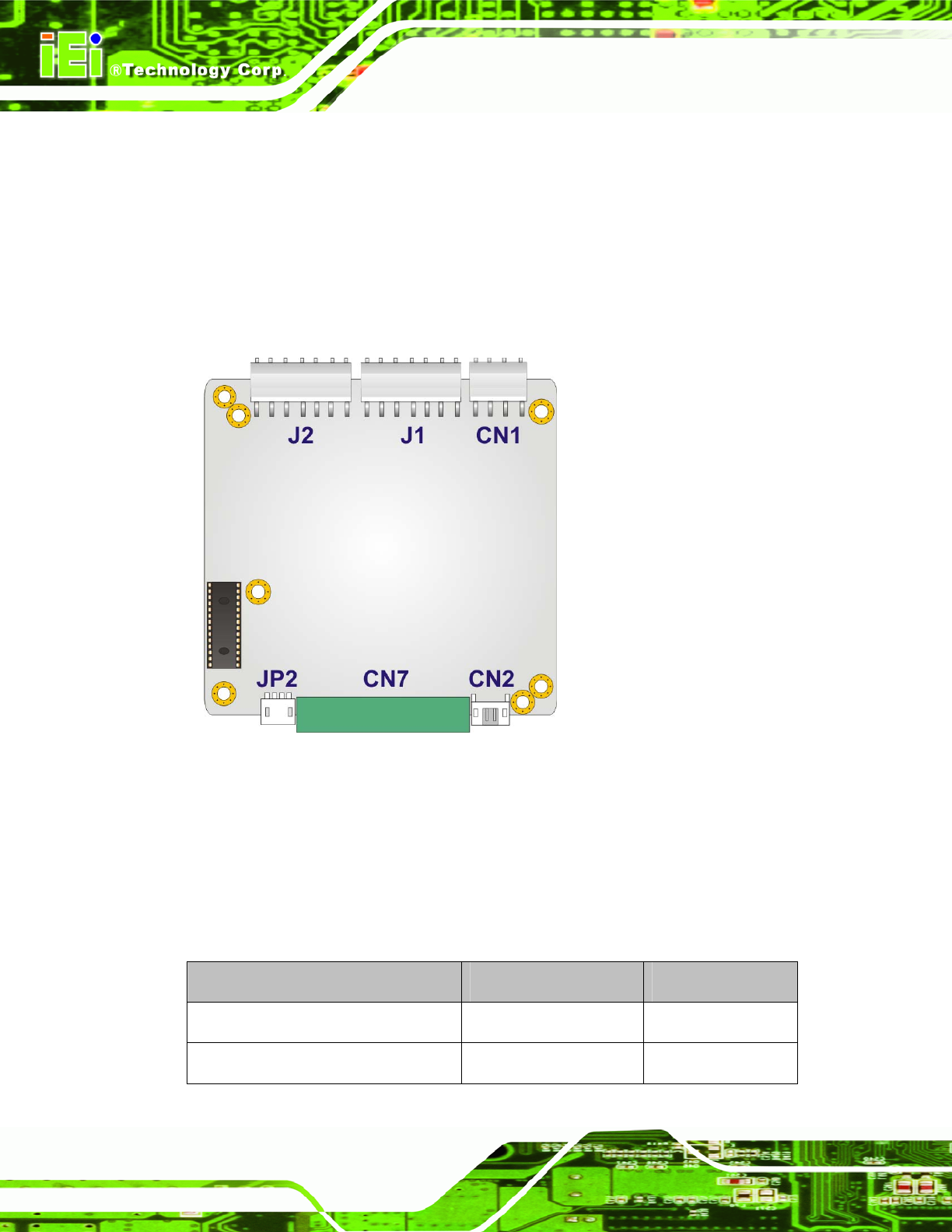
161H161H169HFigure 4-1 shows the on-board peripheral connectors of PM-P006UPS.
Figure 4-1: PM-P006UPS Connector Locations
4.1.2 Peripheral Interface Connectors
162H162H170HTable 4-1 shows a list of the peripheral interface connectors on the PM-P006UPS.
Detailed descriptions of these connectors can be found below.
Connector Type Label
ATX mode connector 4-pin wafer connector CN2
Battery connector (1) 7-pin wafer connector J1