User Manual
Manuals
Brands
IEI Integration Manuals
Hardware
PM-P006UPS
41
42
43
44
45
46
47
48
49
50
Table Of Contents
PM-P006UPS DC/DC Converter Module
1 Introduction
1.1 PM-P006UPS Overview
1.2 PM-P006UPS Power Module Features
1.3 PM-P006UPS Dimensions
2 Detailed Specifications
2.1 PM-P006UPS System Block Diagram
2.2 Safety
2.3 Battery Specifications
3 Unpacking
3.1 Anti-static Precautions
3.2 Unpacking
3.2.1 Unpacking Precautions
3.3 Unpacking Checklist
3.3.1 Package Contents
3.3.2 Optional Items
4 Connector Pinouts
4.1 Peripheral Interface Connectors
4.1.1 PM-P006UPS Layout
4.1.2 Peripheral Interface Connectors
4.2 Internal Peripheral Connectors
4.2.1 ATX Mode Connector
4.2.2 Battery Connectors
4.2.3 Input Power Connector
4.2.4 Output Power Connectors
4.2.5 RS-232 Cable Connector
5 Software Application
5.1 Introduction
5.2 Monitoring DC Power and Smart Battery
5.2.1 Using the Application
5.2.2 Status Information
5.2.2.1 DC Detection
5.2.2.2 Battery Detection
5.2.2.3 Battery Remaining Time
5.2.3 Battery Information
5.2.4 Setting
5.3 System Log
5.4 Exit
A Hazardous Materials Disclosure
A.1 Hazardous Material Disclosure Table for IPB Products Certified as RoHS Compliant Under 2002/95/EC Without Mercury
B Index
PM-P006UPS DC/DC Converter Module
Page 34
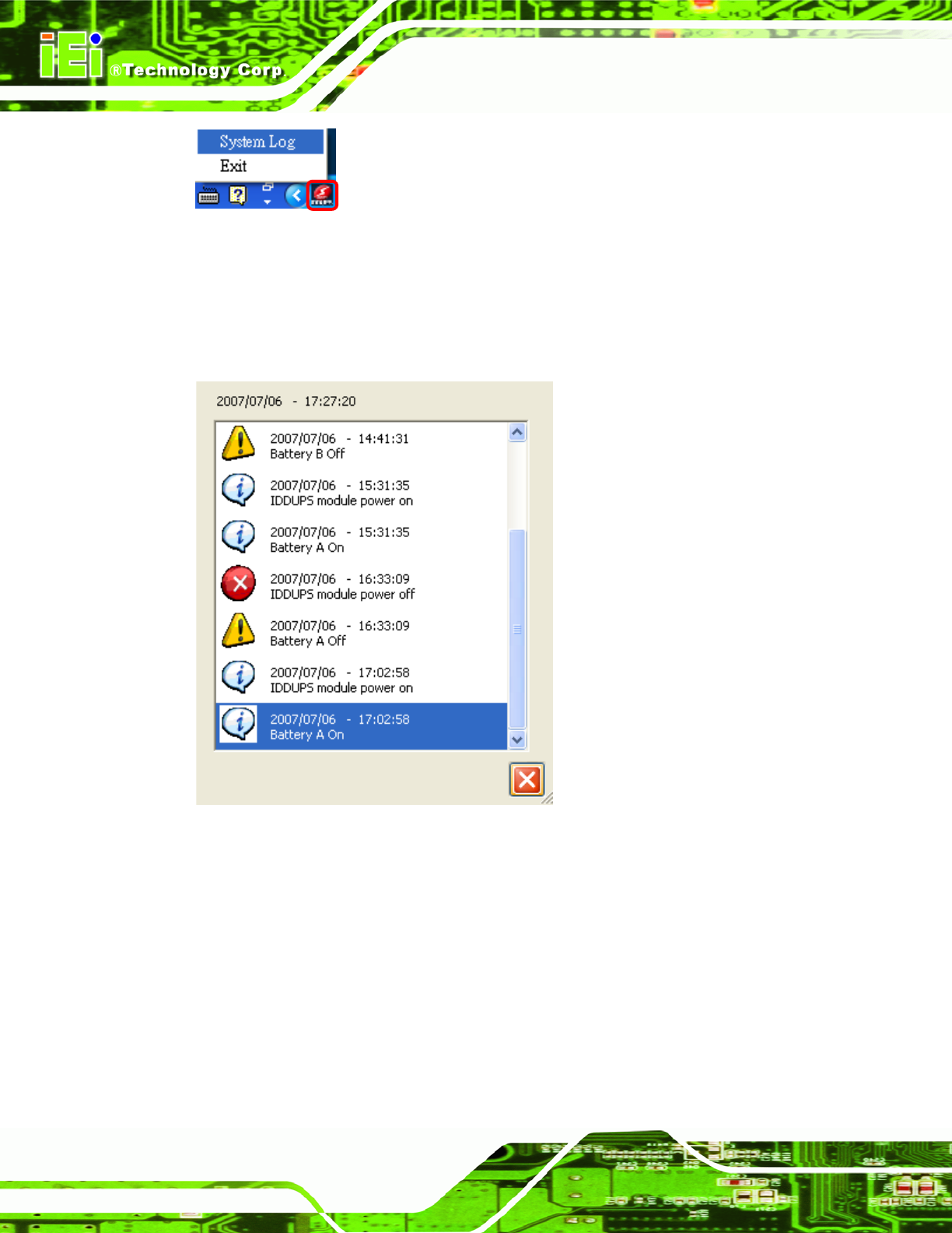
Figure 5-13: IDDUPS Application Quick Launch Icon
After clicking on the Syst
em Log, a screen pops-up (
185H185H197H
Figure 5-14
) and displays all events
that have happened.
Figure 5-14: System Log Example
1
...
...
40
41
42
43
44
...
...
50