
Instruction Manual


PM-PV-D4251/N4551/D5251 User Manual
Page 16
3.1 Peripheral Interface Connectors
The locations of the peripheral interface connectors are shown below.
3.1.1 Layout
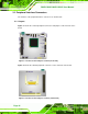
Figure 3-1 shows the on-board peripheral connectors and jumpers on the front side of the
board.
Figure 3-1: Connector and Jumper Locations (Front Side)
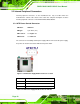
Figure 3-2 shows the onboard peripheral connectors on the solder side of the board.
Figure 3-2: Connector and Jumper Locations (Solder Side)