
Instruction Manual


PM-PV-D4251/N4551/D5251 User Manual
Page 22
Pin Description Pin Description
1 GND 2 VCC
3 Output 3 4 Output 2
5 Output 1 6 Output 0
7 Input 3 8 Input 2
9 Input 1 10 Input 0
Table 3-5: Digital I/O Connector Pinouts
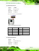
3.2.5 Fan Connector
CN Label: CPU_FAN1
CN Type:
3-pin wafer (1x3)
CN Location:
See
Figure 3-7
CN Pinouts:
See
Table 3-6
The fan connector attaches to a cooling fan.
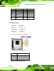
Figure 3-7: Fan Connector Location
Pin Description
1 GND
2 +12V (PWM)
3 FANIO1
Table 3-6: Fan Connector Pinouts