
Instruction Manual


PM-PV-D4251/N4551/D5251 User Manual
Page 23
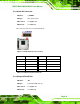
3.2.6 Front Panel Connector
CN Label: F_PANEL1
CN Type:
10-pin header (1x10)
CN Location:
See
Figure 3-8
CN Pinouts:
See
Table 3-7
The front panel connector connects to the indicator LEDs and buttons on the computer's
front panel.
Figure 3-8: Front Panel Connector Location
Function Pin Description
5 V 1 VCC
2 LED-
Power 3 PWR_LED+
LED 4 PWR_LED-
Hard drive 5 HDD_LED+
LED 6 HDD_LED-
Power 7 PWR_BTN+
Button 8 PWR_BTN-
Reset 9 RESET+
10 RESET-
Table 3-7: Front Panel Connector Pinouts