
Instruction Manual


PM-PV-D4251/N4551/D5251 User Manual
Page 49
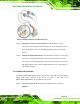
Figure 4-9: Keyboard/mouse Y-cable Connection
Step 4: Attach PS/2 connectors to the chassis. The keyboard/mouse Y-cable
connector is connected to two PS/2 connectors. To secure the PS/2 connectors
to the chassis please refer to the installation instructions that came with the
chassis.
Step 5: Connect the keyboard and mouse. Once the PS/2 connectors are connected
to the chassis, a keyboard and mouse can each be connected to one of the
PS/2 connectors. The keyboard PS/2 connector and mouse PS/2 connector are
both marked. Please make sure the keyboard and mouse are connected to the
correct PS/2 connector. Step 0:
4.8.2 LVDS LCD Installation
The PM-PV-D4251/N4551/D5251 can be connected to a TFT LCD screen through the
30-pin LVDS crimp connector on the board. To connect a TFT LCD to the
PM-PV-D4251/N4551/D5251, please follow the steps below.
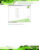
Step 1: Locate the connector. The location of the LVDS connector is shown in
Chapter 3.