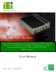
TANK-600 Em b e d de d S ys te m IEI Te c h n o lo g y Co rp . MODEL: TANK-600 S e rie s Fa n le s s Em b e d d e d S ys te m with In te l® Du a l Co re D2550 1.86 GHz p ro c e s s o r / In te l® Du a l Co re N2600 1.6 GHz p ro c e s s o r, VGA, Two Gig a b it Eth e rn e t, S ix US B 2.0, RS -232/422/485, Ro HS Co m p lia n t Us e r Ma n u a l Page i Re v. 1.
TANK-600 Em b e d d e d S ys te m Re vis io n Date Version Changes 7 June 2013 1.02 Add Section 3.3 Mounting the System with Mounting Brackets 24 May 2013 1.01 Update power input in spec. 7 April 2013 1.
TANK-600 Em b e d de d S ys te m Co p yrig h t COP YRIGHT NOTICE The information in this document is subject to change without prior notice in order to improve reliability, design and function and does not represent a commitment on the part of the manufacturer. In no event will the manufacturer be liable for direct, indirect, special, incidental, or consequential damages arising out of the use or inability to use the product or documentation, even if advised of the possibility of such damages.
TANK-600 Em b e d d e d S ys te m Ta b le o f Co n te n ts 1 INTRODUCTION.......................................................................................................... 1 1.1 OVERVIEW.................................................................................................................. 2 1.2 MODEL VARIATIONS ................................................................................................... 3 1.3 FEATURES ................................................................
TANK-600 Em b e d de d S ys te m 3.8.5 VGA Monitor Connection ................................................................................ 25 4 SYSTEM MOTHERBOARD ..................................................................................... 27 4.1 OVERVIEW................................................................................................................ 28 4.1.1 Layout ..............................................................................................................
TANK-600 Em b e d d e d S ys te m 5 BIOS .............................................................................................................................. 39 5.1 INTRODUCTION......................................................................................................... 40 5.1.1 Starting Setup ................................................................................................... 40 5.1.2 Using Setup ..........................................................................
TANK-600 Em b e d de d S ys te m A.2.1 Hardware and BIOS Setup .............................................................................. 77 A.2.2 Create Partitions ............................................................................................. 77 A.2.3 Install Operating System, Drivers and Applications ....................................... 81 A.2.4 Build-up Recovery Partition ............................................................................ 82 A.2.
TANK-600 Em b e d d e d S ys te m Lis t o f Fig u re s Figure 1-1: TANK-600 .....................................................................................................................2 Figure 1-2: TANK-600 Front Panel ................................................................................................5 Figure 1-3: TANK-600 Rear Panel .................................................................................................6 Figure 1-4: Physical Dimensions (millimeters) ........
TANK-600 Em b e d de d S ys te m Figure A-10: Press F3 to Boot into Recovery Mode..................................................................84 Figure A-11: Recovery Tool Menu ..............................................................................................84 Figure A-12: About Symantec Ghost Window ...........................................................................85 Figure A-13: Symantec Ghost Path .................................................................................
TANK-600 Em b e d d e d S ys te m Lis t o f Ta b le s Table 1-1: TANK-600 Model Variations .........................................................................................3 Table 1-2: Technical Specifications ..............................................................................................5 Table 4-1: Peripheral Interface Connectors ...............................................................................29 Table 4-2: Battery Connector Pinouts (BAT1) ............................
TANK-600 Em b e d de d S ys te m Table 4-29: USB 3.0 Connectors Pinouts (USB56) ....................................................................38 Table 4-30: VGA Connector Pinouts (VGA1) .............................................................................38 Table 5-1: BIOS Navigation Keys ................................................................................................
TANK-600 Em b e d de d S ys te m Ch a p te r 1 1 In tro d u c tio n Page 1
TANK-600 Em b e d d e d S ys te m 1.1 Ove rvie w Figure 1-1: TANK-600 The TANK-600 is a fanless embedded system for wide range temperature environments. It is powered by the Intel® dual core D2550 1.86 GHz processor for TANK-600-D2550 or Intel® dual core N2600 1.6 GHz processor for TANK-600-N2600. It has 4.0 GB of DDR3 memory on-board for TANK-600-D2550 and 2.0 GB of DDR3 memory on-board for TANK-600-N2600. The TANK-600 series includes one VGA port, two GbE LAN ports, six USB 2.
TANK-600 Em b e d de d S ys te m 1.2 Mo d e l Va ria tio n s The model variations of the TANK-600 series are listed below. Mo d e l No . CP U Me m o ry TANK-600-CV-D2550-R10 Intel® dual core D2550 1.86 GHz processor 4G DDR3 RAM onboard TANK-600-CV-N2600-R10 Intel® dual core N2600 1.6 GHz 2G DDR3 RAM onboard processor Table 1-1: TANK-600 Model Variations 1.3 Fe a tu re s The TANK-600 features are listed below: Intel® dual core™ D2550 1.86 GHz processor Intel® dual core™ N2600 1.
TANK-600 Em b e d d e d S ys te m S p e c ific a tio n s Mo th e rb o a rd CP U Intel® dual core™ D2550 1.86 GHz processor (TANK-600-CV-D2550-R10) Intel® dual core™ N2600 1.6 GHz processor (TANK-600-CV-N2600-R10) Ch ip s e t Intel® NM10 S ys te m Me m o ry On-board DDR3 4GB (TANK-600-CV-D2550-R10) On-board DDR3 2GB (TANK-600-CV-N2600-R10) S to ra g e Ha rd Drive 1 x 2.5’’ SATA HDD Bay I/O in te rfa c e s US B 2.0 6 x USB2.
TANK-600 Em b e d de d S ys te m S p e c ific a tio n s Op e ra tin g Te m p e ra tu re -20°C ~ 70°C with air flow Op e ra tin g S h o c k Half-sine wave shock 5G, 11ms, 3 shocks per axis Op e ra tin g Vib ra tio n MIL-STD-810F 514.5C-2 (with SSD) We ig h t (Ne t/Gro s s ) 2.2 Kg / 3 Kg S a fe ty/EMC CE / FCC OS Microsoft® WES7E, Microsoft® Windows® XP Embedded S u p p o rte d OS Table 1-2: Technical Specifications 1.
TANK-600 Em b e d d e d S ys te m 2 x RS-232/422/485 serial ports by DB-9 4 x USB 2.0 ports 1 x VGA port 1.6 Re a r P a n e l The rear panel of the TANK-600 has the following features (Figure 1-2): Figure 1-3: TANK-600 Rear Panel Connectors and buttons on the front panel include the following: Page 6 1 x 9 V ~ 36 V DC IN 1 x AT/ATX mode switch 1 x CMOS switch 1 x Reset button 4 x RS-232 serial ports by DB-9 8 x RS-232 serial ports by DB-78 (Optional) 2 x USB 2.
TANK-600 Em b e d de d S ys te m 1.
TANK-600 Em b e d d e d S ys te m Ch a p te r 2 2 Un p a c kin g Page 8
TANK-600 Em b e d de d S ys te m 2.1 An ti-s ta tic P re c a u tio n s WARNING: Failure to take ESD precautions during installation may result in permanent damage to the TANK-600 and severe injury to the user. Electrostatic discharge (ESD) can cause serious damage to electronic components, including the TANK-600. Dry climates are especially susceptible to ESD.
TANK-600 Em b e d d e d S ys te m 2.3 Un pa c kin g Ch e c klis t NOTE: If some of the components listed in the checklist below are missing, please do not proceed with the installation. Contact the IEI reseller or vendor you purchased the TANK-600 from or contact an IEI sales representative directly. To contact an IEI sales representative, please send an email to sales@iei.com.tw.
TANK-600 Em b e d de d S ys te m Qu a n tity Ite m a n d P a rt Nu m b e r Im a g e S ta n d a rd 4 Screw Set 1 DIN-rail mount (P/N: DK-84MB) 1 One Key Recovery CD (P/N: 7B000-000724-RS) 1 Utility CD The following table lists the optional items that can be purchased separately.
TANK-600 Em b e d d e d S ys te m Ch a p te r 3 3 In s ta lla tio n P a g e 12
TANK-600 Em b e d de d S ys te m 3.1 In s ta lla tio n P re c a u tio n s During installation, be aware of the precautions below: Read the user manual: The user manual provides a complete description of the TANK-600, installation instructions and configuration options. DANGER! Disconnect Power: Power to the TANK-600 must be disconnected during the installation process, or before any attempt is made to access the rear panel.
TANK-600 Em b e d d e d S ys te m Figure 3-1: Remove Retention Screws (Rear Panel) S te p 2: Remove five retention screws from the bottom panel, as shown in Figure 3-2. Figure 3-2: Remove Retention Screws (Bottom Panel) S te p 3: Remove ten hex head screws on either side of the connectors from the rear panel, as shown in Figure 3-3.
TANK-600 Em b e d de d S ys te m Figure 3-3: Remove Hex Head Screws (Rear Panel) S te p 4: Remove the bottom cover from the device. S te p 5: Remove the four HDD bracket retention screws (Figure 3-4). Figure 3-4: HDD Bracket Retention Screws S te p 6: Lift the HDD bracket out of the TANK-600. S te p 7: Slide the HDD to the HDD bracket and secure the HDD to the HDD bracket using four retention screws (Figure 3-5).
TANK-600 Em b e d d e d S ys te m Figure 3-5: Inserting the HDD S te p 8: Install the HDD bracket in the same position it was before and fasten the HDD bracket retention screws. S te p 9: Reinstall the bottom cover. 3.3 Mo u n tin g th e S ys te m with Mo u n tin g Bra c ke ts To mount the embedded system onto a wall or some other surface using the two mounting brackets, please follow the steps below. S te p 1: Turn the embedded system to the bottom panel.
TANK-600 Em b e d de d S ys te m Figure 3-6: Mounting Bracket Retention Screws S te p 3: Secure the brackets to the system by inserting two retention screws into each bracket (Figure 3-6). S te p 4: Drill holes in the intended installation surface. S te p 5: Align the mounting holes in the sides of the mounting brackets with the predrilled holes in the mounting surface. S te p 6: Insert four retention screws, two in each bracket, to secure the system to the wall. 3.
TANK-600 Em b e d d e d S ys te m Figure 3-7: AT/ATX Switch Location Adjust the AT/ATX switch. S te p 0: S te p 2: 3.4.1 AT P owe r Mo d e With the AT mode selected, the power is controlled by a central power unit rather than a power switch. The TANK-600 system turns on automatically when the power is connected.
TANK-600 Em b e d de d S ys te m 3.5 Cle a r CMOS If the TANK-600 fails to boot due to improper BIOS settings, the clear CMOS switch clears the CMOS data and resets the system BIOS information. To do this, adjust the clear CMOS switch to clear CMOS mode for a few seconds then reinstall the clear CMOS switch back to keep CMOS mode. S te p 1: Locate the clear CMOS switch on the bottom panel (Figure 3-8). Figure 3-8: Clear CMOS Switch Location S te p 2: Adjust the clear CMOS switch. S te p 0: 3.
TANK-600 Em b e d d e d S ys te m Press the reset button. S te p 0: S te p 2: 3.7 P owe rin g On /Off th e S ys te m WARNING: Make sure a power supply with the correct input voltage is being fed into the system. Incorrect voltages applied to the system may cause damage to the internal electronic components and may also cause injury to the user. Power on the system: press the power button for 3 seconds Power off the system: press the power button for 6 seconds Figure 3-10: Power Button 3.
TANK-600 Em b e d de d S ys te m To install these devices, connect the corresponding cable connector from the actual device to the corresponding TANK-600 external peripheral interface connector making sure the pins are properly aligned. 3.8.1 Au d io Co n n e c tio n The audio jacks on the external audio connector enable the TANK-600 to be connected to a stereo sound setup. To install the audio devices, follow the steps below. Identify the audio plugs.
TANK-600 Em b e d d e d S ys te m 3.8.2 LAN Co n n e c tio n There are two external RJ-45 LAN connectors on the TANK-600. The RJ-45 connector enables connection to an external network. To connect a LAN cable with an RJ-45 connector, please follow the instructions below. S te p 1: Locate the RJ-45 connectors. The location of the LAN connector is shown in Chapter 1. S te p 2: Align the connectors. Align the RJ-45 connector on the LAN cable with one of the RJ-45 connectors on the TANK-600. See Figure 3-12.
TANK-600 Em b e d de d S ys te m 3.8.3.1 DB-9 S e ria l P o rt Co n n e c tio n Follow the steps below to connect a serial device to the DB-9 connector of the TANK-600 system. S te p 1: Locate the DB-9 connector. The locations of the DB-9 connectors are shown in Chapter 1. S te p 2: Insert the serial connector. Insert the DB-9 connector of a serial device into the DB-9 connector on the bottom panel. See Figure 3-13. Figure 3-13: DB-9 Serial Port Connection S te p 3: Secure the connector.
TANK-600 Em b e d d e d S ys te m S te p 1: Locate the DB-78 serial port. The location of the DB-78 serial port is shown in Chapter 1. S te p 2: Connect the DB-78 to COM port cable to the system. Insert the DB-78 connector end of cable into the DB-78 serial port. See Figure 3-14. Figure 3-14: DB-78 to COM port cable S te p 3: Connect the serial device. Connect a serial device to the DB-9 connector end of the cable. See Figure 3-13. S te p 4: Secure the connector.
TANK-600 Em b e d de d S ys te m Figure 3-15: USB Device Connection S te p 3: Insert the device connector. Once aligned, gently insert the USB device connector into the onboard connector. S te p 0: 3.8.5 VGA Mo n ito r Co n n e c tio n The TANK-600 has a single female DB-15 connector on the external peripheral interface panel. The DB-15 connector is connected to a CRT or VGA monitor. To connect a monitor to the TANK-600, please follow the instructions below. S te p 1: Locate the female DB-15 connector.
TANK-600 Em b e d d e d S ys te m Figure 3-16: VGA Connector S te p 4: Secure the connector. Secure the DB-15 VGA connector from the VGA monitor to the external interface by tightening the two retention screws on either side of the connector.
TANK-600 Em b e d de d S ys te m Chapter 4 4 S ys te m Mo th e rb o a rd P a g e 27
TANK-600 Em b e d d e d S ys te m 4.1 Ove rvie w This chapter details all the jumpers and connectors of the system motherboard. 4.1.1 La yo u t The figures below show all the connectors and jumpers of the system motherboard. The Pin 1 locations of the on-board connectors are also indicated in the diagram below. Figure 4-1: System Motherboard 4.2 In te rn a l P e rip h e ra l Co n n e c to rs The table below shows a list of the internal peripheral interface connectors on the system motherboard.
TANK-600 Em b e d de d S ys te m Co n n e c to r Typ e La b e l Digital I/O connector 10-pin header SDIO1 EC Debug connector 20-pin wafer LPT_DB1 EC programming connector 6-pin wafer JSPI1 Keyboard/mouse connector 6-pin wafer KB_MS1 PCIe Mini card slot PCIe Mini card slot M_PCIE1, M_PCIE2 Power button connector 4-pin wafer PW_BT1 Power connector 4-pin wafer DC_IN2 SATA 3Gb/s drive connectors 7-pin SATA connector SATA1, SATA2 SATA power connector 2-pin wafer SATA_PWR1, SATA_PWR2
TANK-600 Em b e d d e d S ys te m 4.2.3 Dig ita l I/O Co n n e c to r (S DIO1) PIN NO. DESCRIPTION PIN NO. DESCRIPTION 1 GND 2 +5V 3 DGPO3 4 DGPO2 5 DGPO1 6 DGPO0 7 DGPI3 8 DGPI2 9 DGPI1 10 DGPI0 Table 4-4: Digital I/O Connector Pinouts (SDIO1) 4.2.4 EC De b u g Co n n e c to r (LP T_DB1) PIN NO. DESCRIPTION PIN NO.
TANK-600 Em b e d de d S ys te m 4.2.6 Ke yb o a rd /Mo u s e Co n n e c to r (KB_MS 1) PIN NO. DESCRIPTION PIN NO. DESCRIPTION 1 Power 2 MSDATA_T 3 MSCLK_T 4 KBDATA_T 5 KBCLK_T 6 GND Table 4-7: Keyboard/Mouse Connector Pinouts (KB_MS1) 4.2.7 P owe r Bu tto n Co n n e c to r (P W_BT1) PIN NO. DESCRIPTION PIN NO. DESCRIPTION 1 PWRBTN_SW# 2 GND 3 GND 4 POWER (3.3V) Table 4-8: Power Button Connector Pinouts (PW_BT1) 4.2.8 P owe r Co n n e c to r (DC_IN2) PIN NO.
TANK-600 Em b e d d e d S ys te m 3 SATA_T_CN_TX- 4 GND 5 SATA_T_CN_RX-- 6 SATA_T_CN_RX+ 7 GND Table 4-11: SATA 3Gb/s Drive Connectors Pinouts (SATA2) 4.2.11 S ATA P o we r Co n n e c to r (S ATA_P WR1, S ATA_P WR2) PIN NO. DESCRIPTION PIN NO. DESCRIPTION 1 +5V 2 GND Table 4-12: SATA Power Connector Pinouts (SATA_PWR1, SATA_PWR2) 4.2.12 S ATA LED Co n n e c to r (S ATA_LED1) PIN NO. DESCRIPTION PIN NO.
TANK-600 Em b e d de d S ys te m 4.3 Exte rn a l In te rfa c e P a n e l Co n n e c to rs The table below shows a list of the external interface panel connectors on the system motherboard. Pinouts of these connectors can be found in the following sections. Co n n e c to r Typ e La b e l Audio jack (mic, line-out) Audio jack JAUDIO1 Ethernet and USB2.0 connectors RJ-45, USB 2.
TANK-600 Em b e d d e d S ys te m P5 LAN1_MDI1- P6 LAN1_MDI2+ P7 LAN1_MDI2- P8 LAN1_MDI3+ P9 LAN1_MDI3- P10 GND P 11 LAN1_LED_100M P 12 LAN1_LED_1000M P 13 LAN1_LED_ACT P 14 Power 1 +V5A_IO_USB01 2 USB0_T_D- 3 USB0_T_D+ 4 GND 5 +V5A_IO_USB01 6 USB1_T_D- 7 USB1_T_D+ 8 GND Table 4-17: Ethernet and USB2.0 Connectors Pinouts (USBLAN1) 4.3.3 Eth e rn e t a n d US B2.0 Co n n e c to rs (US BLAN2) PIN NO. DESCRIPTION PIN NO.
TANK-600 Em b e d de d S ys te m 4.3.5 RS -232 S e ria l P o rt Co n n e c to r (COM1) PIN NO. RS-232 RS-422 RS-485 1 COM1_DCD# TXD422#1 TXD485#1 2 COM1_RXD TXD422+1 TXD485+1 3 COM1_TXD RXD422+1 NA 4 COM1_DTR# RXD422#1 NA 5 GND NA NA 6 COM1_DSR# NA NA 7 COM1_RTS# NA NA 8 COM1_CTS# NA NA 9 COM1_RI# NA NA Table 4-20: RS-232 Serial Port Connector Pinouts (COM1) 4.3.6 RS -232 S e ria l P o rt Co n n e c to r (COM2) PIN NO.
TANK-600 Em b e d d e d S ys te m 7 COM3_RTS# 9 COM3_RI# 8 COM3_CTS# Table 4-22: RS-232 Serial Port Connector Pinouts (COM3) 4.3.8 RS -232 S e ria l P o rt Co n n e c to r (COM4) PIN NO. DESCRIPTION PIN NO. DESCRIPTION 1 COM4_DCD# 2 COM4_RXD 3 COM4_TXD 4 COM4_DTR# 5 GND 6 COM4_DSR# 7 COM4_RTS# 8 COM4_CTS# 9 COM4_RI# Table 4-23: RS-232 Serial Port Connector Pinouts (COM4) 4.3.9 RS -232 S e ria l P o rt Co n n e c to r (COM5) PIN NO. DESCRIPTION PIN NO.
TANK-600 Em b e d de d S ys te m 4.3.11 RS -232 S e ria l P o rt Co n n e c to r (COM7) PIN NO. DESCRIPTION PIN NO. DESCRIPTION 1 COM7_DCD# 2 COM7_RXD 3 COM7_TXD 4 COM7_DTR# 5 GND 6 COM7_DSR# 7 COM7_RTS# 8 COM7_CTS# 9 COM7_RI# Table 4-26: RS-232 Serial Port Connector Pinouts (COM6) 4.3.12 RS -232 S e ria l P o rt Co n n e c to r (COM8) PIN NO. DESCRIPTION PIN NO.
TANK-600 Em b e d d e d S ys te m 4.3.14 US B 2.0 Co n n e c to rs (US B56) PIN NO. DESCRIPTION PIN NO. DESCRIPTION 1 +V5A_IO_USB45 2 -DATA6 3 +DATA6 4 GND 5 +V5A_IO_USB45 6 -DATA7 7 +DATA7 8 GND Table 4-29: USB 3.0 Connectors Pinouts (USB56) 4.3.15 VGA Co n n e c to r (VGA1) PIN NO. DESCRIPTION PIN NO.
TANK-600 Em b e d de d S ys te m Ch a p te r 5 5 BIOS P a g e 39
TANK-600 Em b e d d e d S ys te m 5.1 In tro d u c tio n The BIOS is programmed onto the BIOS chip. The BIOS setup program allows changes to certain system settings. This chapter outlines the options that can be changed. 5.1.1 Sta rtin g S e tu p The UEFI BIOS is activated when the computer is turned on. The setup program can be activated in one of two ways. 1. Press the DEL or F2 key as soon as the system is turned on or 2.
TANK-600 Em b e d de d S ys te m Ke y Fu n c tio n Esc key Main Menu – Quit and not save changes into CMOS Status Page Setup Menu and Option Page Setup Menu -Exit current page and return to Main Menu F1 General help, only for Status Page Setup Menu and Option Page Setup Menu F2 Previous values F3 Load optimized defaults F4 Save changes and Exit BIOS Table 5-1: BIOS Navigation Keys 5.1.
TANK-600 Em b e d d e d S ys te m 5.2 Ma in The Main BIOS menu (BIOS Menu 1) appears when the BIOS Setup program is entered. The Main menu gives an overview of the basic system information. Aptio Setup Utility – Copyright (C) 2011 American Megatrends, Inc. Main Advanced Chipset Boot Security Save & Exit BIOS Information BIOS Vendor Core Version Compliency Project Version Build Date and Time American Megatrends 4.6.5.3 0.16 UEFI 2.3; PI 1.2 SE64AR10.
TANK-600 Em b e d de d S ys te m iWDD Ve rs io n The iWDD Version displays the current iWDD version. The fields in iWDD Version cannot be changed. The System Overview field also has two user configurable fields: S ys te m Da te [xx/xx/xx] Use the System Date option to set the system date. Manually enter the day, month and year. S ys te m Tim e [xx:xx:xx] Use the System Time option to set the system time. Manually enter the hours, minutes and seconds. 5.
TANK-600 Em b e d d e d S ys te m Aptio Setup Utility – Copyright (C) 2011 American Megatrends, Inc. Main Advanced Chipset Boot Security Save & Exit > > > > > > > > > > > ACPI Settings RTC Wake Settings Trusted Computing CPU Configuration SATA Configuration USB Configuration F81866 Super IO Configuration H/M Monitor IT8519 Super IO Configuration Serial Port Console Redirection iEi Feature System ACPI Parameters ---------------------- : Select Screen ↑ ↓: Select Item Enter Select +/-: Change Opt.
TANK-600 Em b e d de d S ys te m ACP I S le e p Sta te [S 1 (CP U Sto p Clo c k)] Use the ACPI Sleep State option to specify the sleep state the system enters when it is not being used. S1 (CPU Stop DEFAULT The system enters S1(POS) sleep state. The system appears off. The CPU is stopped; RAM is Clock) refreshed; the system is running in a low power mode. S3 (Suspend The caches are flushed and the CPU is powered to off. Power to the RAM is maintained.
TANK-600 Em b e d d e d S ys te m Wa ke S ys te m with Fixe d Tim e [Dis a b le d ] Use the Wake System with Fixed Time option to specify the time the system should be roused from a suspended state.
TANK-600 Em b e d de d S ys te m Aptio Setup Utility – Copyright (C) 2011 American Megatrends, Inc. Advanced Configuration Security Device Support [Disable] Current Status Information NO Security Device Found Enables or Disables BIOS support for security device. O.S. will not show Security Device. TCG EFI protocol and INTIA interface will not be available. ---------------------: Select Screen ↑ ↓: Select Item Enter Select +/-: Change Opt.
TANK-600 Em b e d d e d S ys te m Aptio Setup Utility – Copyright (C) 2011 American Megatrends, Inc. Advanced CPU Configuration Processor Type EMT64 Processor Speed System Bus Speed Ratio Status Actual Ratio Processor Stepping Microcode Revision L1 Cache RAM L2 Cache RAM Processor Core Hyper-Threading Intel(R) Atom(TM) CPU D2550 @ 1.
TANK-600 Em b e d de d S ys te m Use the Hyper-Threading BIOS option to enable or disable the Intel Hyper-Threading Technology. Disabled Enabled Disables the Intel Hyper-Threading Technology. DEFAULT Enables the Intel Hyper-Threading Technology. 5.3.5 S ATA Co n fig u ra tio n Use the SATA Configuration menu (BIOS Menu 7) to change and/or set the configuration of the SATA devices installed in the system. Aptio Setup Utility – Copyright (C) 2011 American Megatrends, Inc.
TANK-600 Em b e d d e d S ys te m 5.3.6 US B Co n fig u ra tio n Use the USB Configuration menu (BIOS Menu 8) to read USB configuration information and configure the USB settings. Aptio Setup Utility – Copyright (C) 2011 American Megatrends, Inc. Advanced USB Configuration USB Devices: 1 Keyboard Legacy USB Support [Enabled] Enables Legacy USB support. AUTO option disables legacy support if no USB devices are connected. DISABLE option will keep USB devices available only for EFI applications.
TANK-600 Em b e d de d S ys te m Disabled Legacy USB support disabled Auto Legacy USB support disabled if no USB devices are connected 5.3.7 F81866 S u pe r IO Co nfig u ra tio n Use the F81866 Super IO Configuration menu (BIOS Menu 9) to set or change the configurations for the serial ports. Aptio Setup Utility – Copyright (C) 2011 American Megatrends, Inc.
TANK-600 Em b e d d e d S ys te m 5.3.7.1 S e ria l P o rt n Co n fig u ra tio n Use the Serial Port n Configuration menu (BIOS Menu 10) to configure the serial port n. Aptio Setup Utility – Copyright (C) 2011 American Megatrends, Inc. Advanced Serial Port n Configuration Serial Port Device Settings Enable or Disable Serial Port (COM) [Enabled] IO=3F8h; IRQ=4 --------------------: Select Screen ↑ ↓: Select Item Enter Select +/-: Change Opt.
TANK-600 Em b e d de d S ys te m IO=3F8h; Serial Port I/O port address is 3F8h and the interrupt IRQ=3, 4 address is IRQ3, 4 IO=2F8h; Serial Port I/O port address is 2F8h and the interrupt IRQ=3, 4 address is IRQ3, 4 De vic e Mo d e [RS 232] Use the Device Mode option to select the serial port mode. RS232 RS422 Enables serial port RS-422 support. RS485 Enables serial port RS-485 support. DEFAULT Enables serial port RS-232 support. 5.3.7.1.
TANK-600 Em b e d d e d S ys te m IO=2F8h; Serial Port I/O port address is 2F8h and the interrupt IRQ=3, 4 address is IRQ3, 4 De vic e Mo d e [RS 232] Use the Device Mode option to select the serial port mode. RS232 RS422 Enables serial port RS-422 support. RS485 Enables serial port RS-485 support. DEFAULT Enables serial port RS-232 support. 5.3.7.1.
TANK-600 Em b e d de d S ys te m 5.3.7.1.4 S e ria l P o rt 4 Co n fig u ra tio n S e ria l P o rt [En a b le d ] Use the Serial Port option to enable or disable the serial port. Disabled Enabled Disable the serial port DEFAULT Enable the serial port Ch a n g e S e ttin g s [Au to ] Use the Change Settings option to change the serial port IO port address and interrupt address. Auto DEFAULT The serial port IO port address and interrupt address are automatically detected.
TANK-600 Em b e d d e d S ys te m Auto DEFAULT The serial port IO port address and interrupt address are automatically detected. IO=280h; Serial Port I/O port address is 280h and the interrupt IRQ=10 address is IRQ10 IO=280h; Serial Port I/O port address is 280h and the interrupt IRQ=10, 11 address is IRQ10, 11 IO=288h; Serial Port I/O port address is 288h and the interrupt IRQ=10, 11 address is IRQ10, 11 5.3.7.1.
TANK-600 Em b e d de d S ys te m IO=2D8h; Serial Port I/O port address is 2D8h and the interrupt IRQ=10, 11 address is IRQ10, 11 IO=2E0h; Serial Port I/O port address is 2E0h and the interrupt IRQ=10, 11 address is IRQ10, 11 5.3.8 H/W Mo n ito r The H/W Monitor menu (BIOS Menu 11) shows the operating temperature, fan speeds and system voltages. Aptio Setup Utility – Copyright (C) 2011 American Megatrends, Inc.
TANK-600 Em b e d d e d S ys te m 5.3.9 IT8519 S u p e r IO Co n fig u ra tio n Use the IT8519 Super IO Configuration menu (BIOS Menu 12) to set or change the configurations for the serial ports. Aptio Setup Utility – Copyright (C) 2011 American Megatrends, Inc. Advanced IT8519 Super IO Configuration Super IO Chip Set Parameters of Serial Port 7 (COMA) IT8519 > Serial Port 7 Configuration > Serial Port 8 Configuration --------------------: Select Screen ↑ ↓: Select Item Enter Select +/-: Change Opt.
TANK-600 Em b e d de d S ys te m 5.3.9.1.1 S e ria l P o rt 7 Co n fig u ra tio n S e ria l P o rt [En a b le d ] Use the Serial Port option to enable or disable the serial port. Disabled Enabled Disable the serial port DEFAULT Enable the serial port Ch a n g e S e ttin g s [Au to ] Use the Change Settings option to change the serial port IO port address and interrupt address. Auto DEFAULT The serial port IO port address and interrupt address are automatically detected.
TANK-600 Em b e d d e d S ys te m Auto DEFAULT The serial port IO port address and interrupt address are automatically detected. IO=2B8h; Serial Port I/O port address is 2B8h and the interrupt IRQ=11 address is IRQ11 IO=2A8h; Serial Port I/O port address is 2A8h and the interrupt IRQ=10, 11 address is IRQ10, 11 IO=2B8h; Serial Port I/O port address is 2B8h and the interrupt IRQ=10, 11 address is IRQ10, 11 5.3.
TANK-600 Em b e d de d S ys te m Aptio Setup Utility – Copyright (C) 2011 American Megatrends, Inc.
TANK-600 Em b e d d e d S ys te m Aptio Setup Utility – Copyright (C) 2011 American Megatrends, Inc. Advanced COM1 Console Redirection Settings Terminal Type Bits per second Data Bits Parity Stop Bits [ANSI] [115200] [8] [None] [1] Emulation: ANSI: Extended ASCII char set. VT100: ASCII char set. VT100+: Extends VT100 to support color, function keys, etc. VT-UTF8: Uses UTF8 encoding to map Unicode chars onto 1 or more bytes.
TANK-600 Em b e d de d S ys te m 57600 115200 The transmission speed is 57600 DEFAULT The transmission speed is 115200 Da ta Bits [8] Use the Data Bits option to specify the number of data bits. 7 8 Sets the data bits at 7. DEFAULT Sets the data bits at 8. P a rity [No n e ] Use the Parity option to specify the parity bit that can be sent with the data bits for detecting the transmission errors. None Even DEFAULT No parity bit is sent with the data bits.
TANK-600 Em b e d d e d S ys te m 5.3.11 iEi Fe a tu re Use the iEi Feature menu (BIOS Menu 16) to configure the iEi features. Aptio Setup Utility – Copyright (C) 2011 American Megatrends, Inc. Advanced iEi Feature Auto Recovery Function [Disabled] Auto Recovery Function Reboot and recover system automatically within 10 min, when OS crashes. Please install Auto Recovery API service before enabling this function. --------------------: Select Screen ↑ ↓: Select Item Enter Select +/-: Change Opt.
TANK-600 Em b e d de d S ys te m 5.4 Ch ips e t Use the Chipset menu (BIOS Menu 17) to access the Host Bridge and South Bridge configuration menus. WARNING! Setting the wrong values for the Chipset BIOS selections in the Chipset BIOS menu may cause the system to malfunction. Aptio Setup Utility – Copyright (C) 2011 American Megatrends, Inc.
TANK-600 Em b e d d e d S ys te m 5.4.1 Ho s t Brid g e Co n fig u ra tio n Use the Host Bridge menu (BIOS Menu 18) to view the memory information. Aptio Setup Utility – Copyright (C) 2011 American Megatrends, Inc. Chipset ******* Memory Information ******* Memory Frequency 1067 MHz(DDR3) Total Memory 4096 MB DIMM1 4096 MB --------------------: Select Screen ↑ ↓: Select Item Enter Select F1 General Help F2 Previous Values F3 Optimized Defaults F4 Save ESC Exit Version 2.14.1219.
TANK-600 Em b e d de d S ys te m Aza lia Co n tro lle r [En a b le d ] Use the Azalia Controller option to enable or disable the High Definition Audio controller. Disabled HD Audio The onboard High Definition Audio controller is disabled DEFAULT The onboard High Definition Audio controller automatically detected and enabled Min i-P CIe LAN Co n tro lle r [En a b le d ] Use the Mini-PCIe LAN Controller option to enable or disable the mini PCIe LAN controller.
TANK-600 Em b e d d e d S ys te m Bo o tu p Nu m Lo c k Sta te [On ] Use the Bootup NumLock State BIOS option to specify if the number lock setting must be modified during boot up. On DEFAULT Allows the Number Lock on the keyboard to be enabled automatically when the computer system boots up. This allows the immediate use of the 10-key numeric keypad located on the right side of the keyboard. To confirm this, the Number Lock LED light on the keyboard is lit.
TANK-600 Em b e d de d S ys te m Force DEFAULT Sets display mode to force BIOS. BIOS Sets display mode to current. Keep Current UEFI Bo o t [Dis a b le d ] Use the UEFI Boot option to enable or disable to boot from the UEFI devices. Enabled Disabled Boot from UEFI devices is enabled. DEFAULT Boot from UEFI devices is disabled. 5.6 S e c u rity Use the Security menu (BIOS Menu 21) to set system and user passwords. Aptio Setup Utility – Copyright (C) 2011 American Megatrends, Inc.
TANK-600 Em b e d d e d S ys te m Us e r P a s s wo rd Use the User Password to set or change a user password. 5.7 Exit Use the Exit menu (BIOS Menu 22) to load default BIOS values, optimal failsafe values and to save configuration changes. Aptio Setup Utility – Copyright (C) 2011 American Megatrends, Inc. Main Advanced Chipset Boot Security Save & Exit Save Changes and Reset Discard Changes and Reset Exit the system after saving the changes.
TANK-600 Em b e d de d S ys te m S a ve a s Us e r De fa u lts Use the Save as User Defaults option to save the changes done so far as user defaults. Re s to re Us e r De fa u lts Use the Restore User Defaults option to restore the user defaults to all the setup options.
TANK-600 Em b e d d e d S ys te m Ap p e n d ix A A On e Ke y Re c o ve ry P a g e 72
TANK-600 Em b e d de d S ys te m A.1 On e Ke y Re c o ve ry In tro d u c tio n The IEI one key recovery is an easy-to-use front end for the Norton Ghost system backup and recovery tool. This tool provides quick and easy shortcuts for creating a backup and reverting to that backup or reverting to the factory default settings.
TANK-600 Em b e d d e d S ys te m After completing the five initial setup procedures as described above, users can access the recovery tool by pressing while booting up the system. The detailed information of each function is described in Section A.5. NOTE: The initial setup procedures for Linux system are described in Section A.3. A.1.1 S ys te m Re q u ire m e n t NOTE: The recovery CD can only be used with IEI products.
TANK-600 Em b e d de d S ys te m partitions. Please take the following table as a reference when calculating the size of the partition. OS OS Image after Ghost Compression Ratio Windows® 7 7 GB 5 GB 70% Windows® XPE 776 MB 560 MB 70% Windows® CE 6.0 36 MB 28 MB 77% NOTE: Specialized tools are required to change the partition size if the operating system is already installed. A.1.
TANK-600 Em b e d d e d S ys te m o o o o o o o Ubuntu 8.10 (Intrepid) Ubuntu 7.10 (Gutsy) Ubuntu 6.10 (Edgy) Debian 5.0 (Lenny) Debian 4.0 (Etch) SuSe 11.2 SuSe 10.3 NOTE: Installing unsupported OS versions may cause the recovery tool to fail. A.2 S e tu p P ro c e d u re fo r Win d ows Prior to using the recovery tool to backup or restore Windows system, a few setup procedures are required. S te p 1: Hardware and BIOS setup (see Section A.2.1) S te p 2: Create partitions (see Section A.2.
TANK-600 Em b e d de d S ys te m A.2.1 Ha rdwa re a n d BIOS S e tu p S te p 1: Make sure the system is powered off and unplugged. S te p 2: Install a hard drive or SSD in the system. An unformatted and unpartitioned disk is recommended. S te p 3: Connect an optical disk drive to the system and insert the recovery CD. S te p 4: Turn on the system. S te p 5: Press the key as soon as the system is turned on to enter the BIOS.
TANK-600 Em b e d d e d S ys te m Figure A-2: Launching the Recovery Tool S te p 3: The recovery tool setup menu is shown as below. Figure A-3: Recovery Tool Setup Menu S te p 4: P a g e 78 Press <6> then .
TANK-600 Em b e d de d S ys te m Figure A-4: Command Mode S te p 5: The command prompt window appears. Type the following commands (marked in red) to create two partitions. One is for the OS installation; the other is for saving recovery files and images which will be an invisible partition.
TANK-600 Em b e d d e d S ys te m Figure A-5: Partition Creation Commands P a g e 80
TANK-600 Em b e d de d S ys te m NOTE: Use the following commands to check if the partitions were created successfully. S te p 6: Press any key to exit the recovery tool and automatically reboot the system. Please continue to the following procedure: Build-up Recovery Partition. A.2.3 In s ta ll Op e ra tin g S ys te m , Drive rs a n d Ap p lic a tio n s Install the operating system onto the unlabelled partition.
TANK-600 Em b e d d e d S ys te m A.2.4 Bu ild -u p Re c o ve ry P a rtitio n S te p 1: Put the recover CD in the optical drive. S te p 2: Start the system. S te p 3: Boot the system from recovery CD. When prompted, press any key to boot from the recovery CD. It will take a while to launch the recovery tool. Please be patient! Figure A-6: Launching the Recovery Tool S te p 4: When the recovery tool setup menu appears, press <2> then .
TANK-600 Em b e d de d S ys te m S te p 5: The Symantec Ghost window appears and starts configuring the system to build a recovery partition. In this process the partition created for recovery files in Section A.2.2 is hidden and the recovery tool is saved in this partition. Figure A-8: Building the Recovery Partition S te p 6: After completing the system configuration, press any key in the following window to reboot the system. Figure A-9: Press Any Key to Continue S te p 7: Eject the recovery CD.
TANK-600 Em b e d d e d S ys te m A.2.5 Cre a te Fa c to ry De fa u lt Im a g e NOTE: Before creating the factory default image, please configure the system to a factory default environment, including driver and application installations. To create a factory default image, please follow the steps below. S te p 1: Turn on the system. When the following screen displays (Figure A-10), press the key to access the recovery tool.
TANK-600 Em b e d de d S ys te m Figure A-12: About Symantec Ghost Window S te p 4: Use mouse to navigate to the option shown below (Figure A-13). Figure A-13: Symantec Ghost Path S te p 5: Select the local source drive (Drive 1) as shown in Figure A-14. Then click OK.
TANK-600 Em b e d d e d S ys te m Figure A-14: Select a Local Source Drive S te p 6: Select a source partition (Part 1) from basic drive as shown in Figure A-15. Then click OK. Figure A-15: Select a Source Partition from Basic Drive S te p 7: Select 1.2: [Recovery] NTFS drive and enter a file name called iei (Figure A-16). Click Save. The factory default image will then be saved in the selected recovery drive and named IEI.GHO. WARNING: The file name of the factory default image must be iei.GHO.
TANK-600 Em b e d de d S ys te m Figure A-16: File Name to Copy Image to S te p 8: When the Compress Image screen in Figure A-17 prompts, click High to make the image file smaller.
TANK-600 Em b e d d e d S ys te m S te p 9: The Proceed with partition image creation window appears, click Yes to continue. Figure A-18: Image Creation Confirmation S te p 10: The Symantec Ghost starts to create the factory default image (Figure A-19). Figure A-19: Image Creation Process S te p 11: When the image creation completes, a screen prompts as shown in Figure A-20. Click Continue and close the Ghost window to exit the program.
TANK-600 Em b e d de d S ys te m S te p 12: The recovery tool main menu window is shown as below. Press any key to reboot the system. Step0: Figure A-21: Press Any Key to Continue A.3 Au to Re c o ve ry S e tu p P ro c e d u re The auto recovery function allows a system to automatically restore from the factory default image after encountering a Blue Screen of Death (BSoD) or a hang for around 10 minutes. To use the auto recovery function, follow the steps described in the following sections.
TANK-600 Em b e d d e d S ys te m Figure A-22: Auto Recovery Utility S te p 3: Reboot the system from the recovery CD. When prompted, press any key to boot from the recovery CD. It will take a while to launch the recovery tool. Please be patient! Figure A-23: Launching the Recovery Tool S te p 4: When the recovery tool setup menu appears, press <4> then .
TANK-600 Em b e d de d S ys te m S te p 5: The Symantec Ghost window appears and starts configuring the system to build an auto recovery partition. In this process the partition created for recovery files in Section A.2.2 is hidden and the auto recovery tool is saved in this partition. Figure A-25: Building the Auto Recovery Partition S te p 6: After completing the system configuration, the following message prompts to confirm whether to create a factory default image.
TANK-600 Em b e d d e d S ys te m S te p 7: The Symantec Ghost starts to create the factory default image (Figure A-27). Figure A-27: Image Creation Complete S te p 8: After completing the system configuration, press any key in the following window to restart the system. Figure A-28: Press any key to continue S te p 9: Eject the One Key Recovery CD and restart the system. S te p 10: Press the key as soon as the system is turned on to enter the BIOS.
TANK-600 Em b e d de d S ys te m Main Advanced PCIPNP BIOS SETUP UTILITY Boot Security Chipset Exit iEi Feature Auto Recovery Function [Enabled] Recover from PXE [Disabled] ↑ ↓ Enter F1 F10 ESC Select Screen Select Item Go to SubScreen General Help Save and Exit Exit v02.61 ©Copyright 1985-2006, American Megatrends, Inc. BIOS Menu 23: IEI Feature S te p 12: Save changes and restart the system.
TANK-600 Em b e d d e d S ys te m Install Linux operating system. Make sure to install GRUB (v0.97 or earlier) S te p 2: MBR type and Ext3 partition type. Leave enough space on the hard drive to create the recover partition later. NOTE: If the Linux OS is not installed with GRUB (v0.97 or earlier) and Ext3, the Symantec Ghost may not function properly.
TANK-600 Em b e d de d S ys te m DISKPART>create part pri size= ___ DISKPART>assign letter=N DISKPART>exit system32>format N: /fs:ntfs /q /v:Recovery /y system32>exit S te p 4: Build-up recovery partition. Press any key to boot from the recovery CD. It will take a while to launch the recovery tool. Please be patient. When the recovery tool setup menu appears, type <3> and press (Figure A-30). The Symantec Ghost window appears and starts configuring the system to build-up a recovery partition.
TANK-600 Em b e d d e d S ys te m Figure A-31: Access menu.lst in Linux (Text Mode) S te p 6: Modify the menu.lst as shown below. S te p 7: The recovery tool menu appears. (Figure A-32) Figure A-32: Recovery Tool Menu S te p 8: Create a factory default image. Follow Step 2 ~ Step 12 described in Section A.2.5 to create a factory default image.
TANK-600 Em b e d de d S ys te m A.5 Re c o ve ry To o l Fu n c tio n s After completing the initial setup procedures as described above, users can access the recovery tool by pressing while booting up the system. However, if the setup procedure in Section A.3 has been completed and the auto recovery function is enabled, the system will automatically restore from the factory default image without pressing the F3 key. The recovery tool main menu is shown below.
TANK-600 Em b e d d e d S ys te m WARNING: All data in the system will be deleted during the system recovery. Please backup the system files before restoring the system (either Factory Restore or Restore Backup). A.5.1 Fa c to ry Re s to re To restore the factory default image, please follow the steps below. S te p 1: Type <1> and press in the main menu. S te p 2: The Symantec Ghost window appears and starts to restore the factory default. A factory default image called iei.
TANK-600 Em b e d de d S ys te m Figure A-35: Recovery Complete Window A.5.2 Ba c ku p S ys te m To backup the system, please follow the steps below. S te p 1: Type <2> and press in the main menu. S te p 2: The Symantec Ghost window appears and starts to backup the system. A backup image called iei_user.GHO is created in the hidden Recovery partition. Figure A-36: Backup System S te p 3: The screen is shown as in Figure A-37 when system backup is completed. Press any key to reboot the system.
TANK-600 Em b e d d e d S ys te m Figure A-37: System Backup Complete Window A.5.3 Re s to re Yo u r La s t Ba c ku p To restore the last system backup, please follow the steps below. S te p 1: Type <3> and press in the main menu. S te p 2: The Symantec Ghost window appears and starts to restore the last backup image (iei_user.GHO). Figure A-38: Restore Backup S te p 3: The screen is shown as in Figure A-39 when backup recovery is completed. Press any key to reboot the system.
TANK-600 Em b e d de d S ys te m Figure A-39: Restore System Backup Complete Window A.5.4 Ma n u a l To restore the last system backup, please follow the steps below. S te p 4: Type <4> and press in the main menu. S te p 5: The Symantec Ghost window appears. Use the Ghost program to backup or recover the system manually. Figure A-40: Symantec Ghost Window S te p 6: When backup or recovery is completed, press any key to reboot the system.
TANK-600 Em b e d d e d S ys te m A.6 Re s to re S ys te m s fro m a Lin u x S e rve r thro u g h LAN The One Key Recovery allows a client system to automatically restore to a factory default image saved in a Linux system (the server) through LAN connectivity after encountering a Blue Screen of Death (BSoD) or a hang for around 10 minutes. To be able to use this function, the client system and the Linux system MUST reside in the same domain.
TANK-600 Em b e d de d S ys te m A.6.1 Co n fig u re DHCP S e rve r S e ttin g s S te p 1: Install the DHCP #yum install dhcp (CentOS, commands marked in red) #apt-get install dhcp3-server (Debian, commands marked in blue) S te p 2: Confirm the operating system default settings: dhcpd.conf. CentOS Use the following command to show the DHCP server sample location: #vi /etc/dhcpd.conf The DHCP server sample location is shown as below: Use the following command to copy the DHCP server sample to etc/dhcpd.
TANK-600 Em b e d d e d S ys te m filename “pxelinux.0”; A.6.2 Co n fig u re TFTP S e ttin g s S te p 1: Install the tftp, httpd and syslinux. #yum install tftp-server httpd syslinux (CentOS) #apt-get install tftpd-hpa xinetd syslinux (Debian) S te p 2: Enable the TFTP server by editing the “/etc/xinetd.d/tftp” file and make it use the remap file. The “-vvv” is optional but it could definitely help on getting more information while running the remap file. For example: CentOS #vi /etc/xinetd.
TANK-600 Em b e d de d S ys te m Debian Replace the TFTP settings from “inetd” to “xinetd” and annotate the “inetd” by adding “#”. #vi /etc/inetd.conf Modify: #tftp dgram udp wait root /usr/sbin....... (as shown below) #vi /etc/xinetd.d/tftp A.6.3 Co n fig u re On e Ke y Re c o ve ry S e rve r S e ttin g s S te p 1: Copy the Utility/RECOVERYR10.TAR.BZ2 package from the One Key Recovery CD to the system (server side). S te p 2: Extract the recovery package to /. #cp RecoveryR10.tar.
TANK-600 Em b e d d e d S ys te m A.6.4 Sta rt th e DHCP, TFTP a n d HTTP Start the DHCP, TFTP and HTTP. For example: CentOS #service xinetd restart #service httpd restart #service dhcpd restart Debian #/etc/init.d/xinetd reload #/etc/init.d/xinetd restart #/etc/init.d/dhcp3-server restart A.6.5 Cre a te S ha re d Dire c to ry S te p 1: Install the samba. #yum install samba S te p 2: Create a shared directory for the factory default image. #mkdir /share #cd /share #mkdir /image #cp iei.
TANK-600 Em b e d de d S ys te m Modify: [image] comment = One Key Recovery path = /share/image browseable = yes writable = yes public = yes create mask = 0644 directory mask = 0755 S te p 4: Edit “/etc/samba/smb.conf” for your environment. For example: S te p 5: Modify the hostname #vi /etc/hostname Modify: RecoveryServer A.6.6 S e tu p a Clie n t S ys te m fo r Au to Re c o ve ry S te p 1: Configure the following BIOS options of the client system.
TANK-600 Em b e d d e d S ys te m S te p 2: Continue to configure the Boot Option Priorities BIOS option of the client system: Boot Option #1 remain the default setting to boot from the original OS. Boot Option #2 select the boot from LAN option. S te p 3: Save changes and exit BIOS menu. Exit Save Changes and Exit S te p 4: Install the auto recovery utility into the system by double clicking the Utility/AUTORECOVERY-SETUP.exe in the One Key Recovery CD.
TANK-600 Em b e d de d S ys te m NOTE: A firewall or a SELinux is not in use in the whole setup process. If there is a firewall or a SELinux protecting the system, modify the configuration information to accommodate them.
TANK-600 Em b e d d e d S ys te m A.7 Oth e r In fo rm a tio n A.7.1 Us in g AHCI Mo d e o r ALi M5283 / VIA VT6421A Co n tro lle r When the system uses AHCI mode or some specific SATA controllers such as ALi M5283 or VIA VT6421A, the SATA RAID/AHCI driver must be installed before using one key recovery. Please follow the steps below to install the SATA RAID/AHCI driver. S te p 1: Copy the SATA RAID/AHCI driver to a floppy disk and insert the floppy disk into a USB floppy disk drive.
TANK-600 Em b e d de d S ys te m S te p 5: When the following window appears, press to select “Specify Additional Device”. S te p 6: In the following window, select a SATA controller mode used in the system. Then press . The user can now start using the SATA HDD.
TANK-600 Em b e d d e d S ys te m After pressing , the system will get into the recovery tool setup menu. S te p 7: Continue to follow the setup procedure from Step 4 in Section A.2.2 Create Partitions to finish the whole setup process.Step0: A.7.2 S ys te m Me m o ry Re q u ire m e n t To be able to access the recovery tool by pressing while booting up the system, please make sure to have enough system memory. The minimum memory requirement is listed below.
TANK-600 Em b e d de d S ys te m Ap p e n d ix B B S a fe ty P re c a u tio n s P a g e 113
TANK-600 Em b e d d e d S ys te m B.1 S a fe ty P re c a u tio n s WARNING: The precautions outlined in this appendix should be strictly followed. Failure to follow these precautions may result in permanent damage to the TANK-600. Please follow the safety precautions outlined in the sections that follow: B.1.1 Ge n e ra l S a fe ty P re c a u tio n s Please ensure the following safety precautions are adhered to at all times.
TANK-600 Em b e d de d S ys te m Electrostatic discharge (ESD) can cause serious damage to electronic components, including the TANK-600. Dry climates are especially susceptible to ESD. It is therefore critical that whenever the TANK-600 is opened and any of the electrical components are handled, the following anti-static precautions are strictly adhered to. Wear an anti-static wristband: Wearing a simple anti-static wristband can help to prevent ESD from damaging any electrical component.
TANK-600 Em b e d d e d S ys te m monitors and electrical accessories, such as signal cables or power cords. When you need to dispose of your display products, please follow the guidance of your local authority, or ask the shop where you purchased the product. The mark on electrical and electronic products only applies to the current European Union Member States. Please follow the national guidelines for electrical and electronic product disposal. B.
TANK-600 Em b e d de d S ys te m Vacuum cleaner – Using a vacuum specifically designed for computers is one of the best methods of cleaning the TANK-600. Dust and dirt can restrict the airflow in the TANK-600 and cause its circuitry to corrode. Cotton swabs - Cotton swaps moistened with rubbing alcohol or water are excellent tools for wiping hard to reach areas. Foam swabs - Whenever possible, it is best to use lint free swabs such as foam swabs for cleaning.
TANK-600 Em b e d d e d S ys te m Ap p e n d ix C C Ha za rd o u s Ma te ria ls Dis c lo s u re P a g e 118
TANK-600 Em b e d de d S ys te m C.1 Ha za rd o u s Ma te ria ls Dis c lo s u re Ta ble for IP B P ro d u c ts Ce rtifie d a s Ro HS Co m p lia n t Un d e r 2002/95/EC With o u t Me rc u ry The details provided in this appendix are to ensure that the product is compliant with the Peoples Republic of China (China) RoHS standards. The table below acknowledges the presences of small quantities of certain materials in the product, and is applicable to China RoHS only.
TANK-600 Em b e d d e d S ys te m P a rt Na m e To xic o r Ha za rd o u s S u b s ta n c e s a n d Ele m e n ts Le a d Me rc u ry Ca d m iu m He xa va le n t P o lyb ro m in a te d P o lyb ro m in a te d (P b ) (Hg ) (Cd ) Ch ro m iu m Bip h e n yls Dip h e n yl (CR(VI)) (P BB) Eth e rs (P BDE) Ho u s in g X O O O O X Dis p la y X O O O O X P rin te d Circ u it X O O O O X X O O O O O X O O O O X Fa n As s e m b ly X O O O O X P o we r S u p p ly X O
TANK-600 Em b e d de d S ys te m 此附件旨在确保本产品符合中国 RoHS 标准。以下表格标示此产品中某有毒物质的含量符 合中国 RoHS 标准规定的限量要求。 本产品上会附有”环境友好使用期限”的标签,此期限是估算这些物质”不会有泄漏或突变”的 年限。本 产品可能包含有较短的环境友好使用期限的可替换元件,像是电池或灯管,这些元 件将会单独标示出来。 部件名称 有毒有害物质或元素 铅 汞 镉 六价铬 多溴联苯 多溴二苯 (P b ) (Hg ) (Cd ) (CR(VI)) (P BB) 醚 (P BDE) 壳体 X O O O O X 显示 X O O O O X 印刷电路板 X O O O O X 金属螺帽 X O O O O O 电缆组装 X O O O O X 风扇组装 X O O O O X 电力供应组装 X O O O O X 电池 O O O O O O O: 表示该有毒有害物质在该部件所有物质材料中的含量均在 SJ/T1136