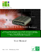
u IBX-210-CV-N2600 Em b e d d e d S ys te m , IEI Te c h n o lo g y Co rp . MODEL: u IBX-210-CV-N2600 S e rie s Fa n le s s Em b e d d e d S ys te m with In te l® Ato m ™ N2600 DC 1.6GHz, In te l® NM10 c h ips e t, P re -in s ta lle d 2GB DDR3 m e m o ry, VGA, HDMI, Gb E, Fo u r US B 2.0, Th re e COM a n d Ro HS Co m p lia n t Us e r Ma n u a l Page i Re v. 1.
u IBX-210-CV-N2600 Em b e d d e d S ys te m Re vis io n Date Version Changes 28 February 2013 1.01 Update Section 2.3: Packing List 27 December 2012 1.
u IBX-210-CV-N2600 Em b e d d e d S ys te m Co p yrig h t COP YRIGHT NOTICE The information in this document is subject to change without prior notice in order to improve reliability, design and function and does not represent a commitment on the part of the manufacturer. In no event will the manufacturer be liable for direct, indirect, special, incidental, or consequential damages arising out of the use or inability to use the product or documentation, even if advised of the possibility of such damages.
u IBX-210-CV-N2600 Em b e d d e d S ys te m Ta b le o f Co n te n ts 1 INTRODUCTION.......................................................................................................... 1 1.1 OVERVIEW.................................................................................................................. 2 1.2 MODEL VARIATIONS ................................................................................................... 2 1.3 FEATURES ......................................................
u IBX-210-CV-N2600 Em b e d d e d S ys te m 3.8.4 RS-232Serial Port Connection ......................................................................... 28 3.8.5 RS-422/485 Serial Port Connection................................................................. 29 3.8.6 USB Device Connection ................................................................................... 30 3.8.7 VGA Monitor Connection ................................................................................
u IBX-210-CV-N2600 Em b e d d e d S ys te m 5.4 REPLACING COMPONENTS ........................................................................................ 43 5.4.1 Hard Disk Drive (HDD) Replacement ............................................................. 43 5.4.2 Memory Module Replacement ......................................................................... 46 5.4.3 WLAN Card Replacement ................................................................................ 47 6 BIOS ..................
u IBX-210-CV-N2600 Em b e d d e d S ys te m 7.1 AVAILABLE SOFTWARE DRIVERS .............................................................................. 80 7.2 STARTING THE DRIVER PROGRAM ............................................................................ 80 7.3 CHIPSET DRIVER INSTALLATION ............................................................................... 81 7.4 GRAPHIC DRIVER INSTALLATION.............................................................................. 85 7.
u IBX-210-CV-N2600 Em b e d d e d S ys te m C.6.1 Configure DHCP Server Settings .................................................................. 134 C.6.2 Configure TFTP Settings ............................................................................... 135 C.6.3 Configure One Key Recovery Server Settings ............................................... 136 C.6.4 Start the DHCP, TFTP and HTTP ................................................................. 137 C.6.5 Create Shared Directory..........
u IBX-210-CV-N2600 Em b e d d e d S ys te m Lis t o f Fig u re s Figure 1-1: uIBX-210-CV-N2600 .....................................................................................................2 Figure 1-2: uIBX-210-CV-N2600 Front Panel ................................................................................5 Figure 1-3: uIBX-210-CV-N2600 Rear Panel .................................................................................6 Figure 1-4: Physical Dimensions (mm) ............................
u IBX-210-CV-N2600 Em b e d d e d S ys te m Figure 3-27: VGA Connector .......................................................................................................31 Figure 4-1: System Motherboard ................................................................................................33 Figure 5-1: Retention Screws Removal ......................................................................................43 Figure 5-2: HDD Bracket Retention Screws ......................................
u IBX-210-CV-N2600 Em b e d d e d S ys te m Figure C-2: Launching the Recovery Tool ...............................................................................109 Figure C-3: Recovery Tool Setup Menu ...................................................................................109 Figure C-4: Command Prompt ..................................................................................................110 Figure C-5: Partition Creation Commands ....................................................
u IBX-210-CV-N2600 Em b e d d e d S ys te m Figure C-37: System Backup Complete Window ....................................................................131 Figure C-38: Restore Backup ....................................................................................................131 Figure C-39: Restore System Backup Complete Window ......................................................132 Figure C-40: Symantec Ghost Window .............................................................................
u IBX-210-CV-N2600 Em b e d d e d S ys te m Lis t o f Ta b le s Table 1-1: Model Variations ...........................................................................................................2 Table 1-2: Technical Specifications ..............................................................................................5 Table 2-1: Package List Contents ...............................................................................................10 Table 4-1: Peripheral Interface Connectors ....
u IBX-210-CV-N2600 Em b e d d e d S ys te m Ch a p te r 1 1 In tro d u c tio n Page 1
u IBX-210-CV-N2600 Em b e d d e d S ys te m 1.1 Ove rvie w Figure 1-1: uIBX-210-CV-N2600 The uIBX-210-CV-N2600 embedded system is a fanless system with one VGA port and one HDMI port for dual display. It accepts a Intel® N2600 1.6GHz dual-core processor and supports one 204-pin 800 MHz dual-channel DDR3 SDRAM SO-DIMM module up to 2 GB. The uIBX-210-CV-N2600 supports a 2.5” SATA HDD with up to 3 Gb/s data transfer rate. Three serial ports and four external USB 2.
u IBX-210-CV-N2600 Em b e d d e d S ys te m 1.3 Fe a tu re s The uIBX-210-CV-N2600 features are listed below: Slim and compact embedded system design with Intel® 3rd Gen Atom N2600 dual-core processor , Supports DDR3 memory (System Max. 2GB) 12V only single voltage design, supports AT/ATX power mode selection Flexible VGA and HDMI with dual-display support Support PCIe Mini card slot Fully I/O with four USB, one VGA, one HDMI, three COM and audio 1.
u IBX-210-CV-N2600 Em b e d d e d S ys te m S ys te m Fu n c tio n Dis p la y Ou tp u t Support HDMI, VGA for dual independent display Display 1: Analog CRT up to 1920x1200 for Cedarview-D and Cedarview-M, support CRT hot plug Display 2: HDMI up to 1920 x 1200 Eth e rn e t 1 x RJ-45 LAN by Realtek RTL8111E GbE S u p e r I/O Fintek F81866 In d ic a to rs HDD LED / Power LED indicator Fro n t I/Os 1 x HDMI 1 x VGA 2 x USB port 1 x Mic-in 1 x Line-out, Re a r I/Os 2 x USB port 2 x RS-232 (COM 1, COM
u IBX-210-CV-N2600 Em b e d d e d S ys te m Ha rd wa re Mo n ito r Fintek F81865 Op e ra tin g Te m p e ra tu re 0°C ~ 50°C with air flow Mo u n tin g VESA 75 EMC/S a fe ty CE, FCC class A S u p p o rte d OS Microsoft® WES7E Microsoft® Windows® XP Embedded Microsoft® CE 6.0 Table 1-2: Technical Specifications 1.
u IBX-210-CV-N2600 Em b e d d e d S ys te m 1 x AT/ATX Switch 1 x HDD LED 1 x HDMI port 1 x Line out 1 x Mic 1 x Power button 1 x Power LED 1 x Reset button 2 x USB 2.
u IBX-210-CV-N2600 Em b e d d e d S ys te m 1.
u IBX-210-CV-N2600 Em b e d d e d S ys te m Ch a p te r 2 2 Un p a c kin g Page 8
u IBX-210-CV-N2600 Em b e d d e d S ys te m 2.1 An ti-s ta tic P re c a u tio n s WARNING: Failure to take ESD precautions during installation may result in permanent damage to the uIBX-210-CV-N2600 and severe injury to the user. Electrostatic discharge (ESD) can cause serious damage to electronic components, including the uIBX-210-CV-N2600. Dry climates are especially susceptible to ESD.
u IBX-210-CV-N2600 Em b e d d e d S ys te m 2.3 P a c kin g Lis t NOTE: If some of the components listed in the checklist below are missing, please do not proceed with the installation. Contact the IEI reseller or vendor you purchased the uIBX-210-CV-N2600 from or contact an IEI sales representative directly. To contact an IEI sales representative, please send an email to sales@iei.com.tw.
u IBX-210-CV-N2600 Em b e d d e d S ys te m Ch a p te r 3 3 In s ta lla tio n P a g e 11
u IBX-210-CV-N2600 Em b e d d e d S ys te m 3.1 In s ta lla tio n P re c a u tio n s During installation, be aware of the precautions below: Read the user manual: The user manual provides a complete description of the uIBX-210-CV-N2600, installation instructions and configuration options. DANGER! Disconnect Power: Power to the uIBX-210-CV-N2600 must be disconnected during the installation process, or before any attempt is made to access the rear panel.
u IBX-210-CV-N2600 Em b e d d e d S ys te m S te p 2: Install the antennas to the antenna connectors (Figure 3-1). Figure 3-1: Wi-Fi Antenna Installation 3.4 AT/ATX Mo d e S e le c tio n AT or ATX power mode can be used on the uIBX-210-CV-N2600. The selection is made through an AT/ATX switch located on the rear panel (Figure 3-2). To select AT mode or ATX mode, follow the steps below. S te p 1: Locate the AT/ATX switch on the rear panel (Figure 3-2).
u IBX-210-CV-N2600 Em b e d d e d S ys te m 3.4.1 AT P owe r Mo d e With the AT mode selected, the power is controlled by a central power unit rather than a power switch. The uIBX-210-CV-N2600 panel PC turns on automatically when the power is connected.
u IBX-210-CV-N2600 Em b e d d e d S ys te m Figure 3-3: Reset Button Location S te p 2: Press the reset button. S te p 0: 3.6 P owe rin g On th e S ys te m To power on the system, follow the steps below: S te p 1: Press the power button on the front panel (Figure 3-4). S te p 2: Once turned on, the power LED should light up. Figure 3-4: Power Button Location 3.7 Mo u n t th e S ys te m The mounting methods are described below.
u IBX-210-CV-N2600 Em b e d d e d S ys te m 3.7.1 Wa ll Mo u n t To mount the embedded system onto a wall using the optional VESA 75 wall mount kit, please follow the steps below. S te p 1: Select the location on the wall for the wall-mounting bracket. S te p 2: Carefully mark the locations of the four brackets screw holes on the wall. S te p 3: Drill four pilot holes at the marked locations on the wall for the bracket retention screws.
u IBX-210-CV-N2600 Em b e d d e d S ys te m S te p 8: Carefully insert the screws through the holes and gently pull the system downwards until the system rests securely in the slotted holes (Figure 3-6). Ensure that all four of the mounting screws fit snuggly into their respective slotted holes. Figure 3-6: Chassis Support Screws S te p 9: Secure the uIBX-210-CV-N2600 by fastening the retention screw of the wall-mounting bracket. (Figure 3-7).
u IBX-210-CV-N2600 Em b e d d e d S ys te m Figure 3-7: Secure the uIBX-210-CV-N2600 3.7.2 VES A m o u n t 75 To mount the embedded system onto a panel PC (VESA 75 mm), please follow the steps below.
u IBX-210-CV-N2600 Em b e d d e d S ys te m S te p 1: Install the mount kit on the back of the panel PC. Figure 3–9: Mount Kit Installation S te p 2: Slide the uIBX-210-CV-N2600 into the mount kit.
u IBX-210-CV-N2600 Em b e d d e d S ys te m S te p 3: Fasten the four screws on the mount kit. Figure 3–11: Mount Kit Screws S te p 4: Attach the uIBX-210-CV-N2600 to the stand using four retention screws.
u IBX-210-CV-N2600 Em b e d d e d S ys te m 3.7.3 VES A m o u n t 100 To mount the embedded system onto a panel PC (VESA 100 mm), please follow the steps below. Figure 3–13: Panel PC (VESA 100 mm) S te p 1: If the mounting pattern on the panel PC is VESA 100 mm then the adapter must be attached.
u IBX-210-CV-N2600 Em b e d d e d S ys te m S te p 2: Fasten the mount kit onto the VESA mount 100 mm to 75 mm adapter on the back of the panel PC. Figure 3–15: Mount Kit Installation S te p 3: Slide the uIBX-210-CV-N2600 into the mount kit.
u IBX-210-CV-N2600 Em b e d d e d S ys te m S te p 4: Fasten the four screws on the mount kit. Figure 3–17: Mount Kit Screws S te p 5: Attach the uIBX-210-CV-N2600 to the stand using four retention screws. Figure 3–18: Stand Installation 3.8 Exte rn a l P e rip h e ra l In te rfa c e Co n n e c to rs The following external peripheral devices can be connected to the external peripheral interface connectors.
u IBX-210-CV-N2600 Em b e d d e d S ys te m Audio devices DVI devices HDMI devices RJ-45 Ethernet cable connector Serial devices USB devices To install these devices, connect the corresponding cable connector from the actual device to the corresponding uIBX-210-CV-N2600 external peripheral interface connector making sure the pins are properly aligned.
u IBX-210-CV-N2600 Em b e d d e d S ys te m Figure 3-20: Peripheral Connectors (Rear Panel) 3.8.1 Au d io Co n n e c tio n The audio jacks on the external audio connector enable the uIBX-210-CV-N2600 to be connected to a stereo sound setup. To install the audio devices, follow the steps below. Identify the audio plugs. The plugs on your home theater system or speakers S te p 1: may not match the colors on the rear panel. If audio plugs are plugged into the wrong jacks, sound quality will be very bad.
u IBX-210-CV-N2600 Em b e d d e d S ys te m Figure 3-21: Audio Connector S te p 3: Check audio clarity. Check that the sound is coming through the right speakers by adjusting the balance front to rear and left to right. 3.8.2 HDMI De vic e Co n n e c tio n The HDMI connector transmits a digital signal to compatible HDMI display devices such as a TV or computer screen. To connect the HDMI cable to the uIBX-210-CV-N2600, follow the steps below. S te p 1: Locate the HDMI connector.
u IBX-210-CV-N2600 Em b e d d e d S ys te m Figure 3-22: HDMI Connection S te p 3: Insert the HDMI connector. Gently insert the HDMI connector. The connector should engage with a gentle push. If the connector does not insert easily, check again that the connector is aligned correctly, and that the connector is being inserted with the right way up. 3.8.3 LAN Co n n e c tio n There is one external RJ-45 LAN connector. The RJ-45 connector enables connection to an external network.
u IBX-210-CV-N2600 Em b e d d e d S ys te m Figure 3-23: LAN Connection S te p 3: Insert the LAN cable RJ-45 connector. Once aligned, gently insert the LAN cable RJ-45 connector into the RJ-45 connector. S te p 0: 3.8.4 RS -232S e ria l P o rt Con n e c tio n There are two RS-232 DB-9 connectors of the uIBX-210-CV-N2600 for serial device connection. Follow the steps below to connect a serial device to the DB-9 connector of the uIBX-210-CV-N2600. S te p 1: Locate the DB-9 connector.
u IBX-210-CV-N2600 Em b e d d e d S ys te m Figure 3-24: DB-9 Serial Port Connector S te p 3: Secure the connector. Secure the serial device connector to the external interface by tightening the two retention screws on either side of the connector. Step 0: 3.8.5 RS -422/485 S e ria l P ort Co n n e c tio n There is one RS-422/485 serial port of the uIBX-210-CV-N2600 for serial device connection. Follow the steps below to connect a serial device to the RS-422/485 serial port of the uIBX-210-CV-N2600.
u IBX-210-CV-N2600 Em b e d d e d S ys te m Figure 3-25: RS-422/485 Cable S te p 3: Insert the serial connector. Insert the DB-9 connector of a serial device into the DB-9 connector on the RS-422/485 cable. S te p 4: Secure the connector. Secure the serial device connector to the external interface by tightening the two retention screws on either side of the connector. 3.8.6 US B De vic e Co n n e c tio n There are four USB 2.0 connectors on the uIBX-210-CV-N2600.
u IBX-210-CV-N2600 Em b e d d e d S ys te m S te p 3: Insert the device connector. Once aligned, gently insert the USB device connector into the onboard connector. S te p 0: 3.8.7 VGA Mo n ito r Co n n e c tio n The uIBX-210-CV-N2600 has a single female DB-15 connector on the rear panel. The DB-15 connector is connected to a CRT or VGA monitor. To connect a monitor to the uIBX-210-CV-N2600, please follow the instructions below. S te p 1: Locate the female DB-15 connector.
u IBX-210-CV-N2600 Em b e d d e d S ys te m Chapter 4 4 S ys te m Mo th e rb o a rd P a g e 32
u IBX-210-CV-N2600 Em b e d d e d S ys te m 4.1 Ove rvie w This chapter details all the jumpers and connectors of the system motherboard. 4.1.1 La yo u t The figures below show all the connectors and jumpers of the system motherboard. The Pin 1 locations of the on-board connectors are also indicated in the diagram below. Figure 4-1: System Motherboard 4.2 In te rn a l P e rip h e ra l Co n n e c to rs The table below shows a list of the internal peripheral interface connectors on the system motherboard.
u IBX-210-CV-N2600 Em b e d d e d S ys te m Co n n e c to r Typ e La b e l DDR3 SO-DIMM slot DDR3 SO-DIMM slot DIMM1 Debug port connector 9-pin wafer DEBUGCN1 HDD LED connector 2-pin wafer HDDLED1 JSATA connector 20-pin connector JSATA2 PCIe Mini Card Slot PCIe mini card slot MINI_PCIE1 Power LED connector 2-pin wafer PWRLED1 USB 2.
u IBX-210-CV-N2600 Em b e d d e d S ys te m 5 LPC_AD2 6 LPC_AD1 7 LPC_AD0 8 LPC_FRAME# 9 +3.3V Table 4-4: Debug port Connector Pinouts (DEBUGCN1) 4.2.4 HDD LED Co n n e c to r (HDDLED1) PIN NO. DESCRIPTION 1 SATA_LED# 2 +5V Table 4-5: HDD LED Connector Pinouts (HDDLED1) 4.2.5 J S ATA Co n n e c to r (J S ATA2) PIN NO. DESCRIPTION PIN NO.
u IBX-210-CV-N2600 Em b e d d e d S ys te m 4.2.7 US B 2.0 Co n n e c to r (US B4_5) PIN NO. DESCRIPTION PIN NO. DESCRIPTION 1 +5V 2 GND 3 USB_PN5 4 USB_PP6 5 USB_PP5 6 USB_PN6 7 GND 8 +5V Table 4-8: USB 2.0 Connector Pinouts (USB4_5) 4.2.8 S ATA Co n n e c to r (S _ATA1) PIN NO. DESCRIPTION 1 GND 2 SATA_TX0+ 3 SATA_TX0- 4 GND 5 SATA_RX0- 6 SATA_RX0+ 7 GND Table 4-9: SATA Connector Pinouts (S_ATA1) 4.2.9 S ATA P o we r Co n n e c to r (CN1) PIN NO.
u IBX-210-CV-N2600 Em b e d d e d S ys te m 4.3 Exte rn a l In te rfa c e P a n e l Co n n e c to rs The table below shows a list of the external interface panel connectors on the system motherboard. Pinouts of these connectors can be found in the following sections.
u IBX-210-CV-N2600 Em b e d d e d S ys te m 7 MDI2+ 8 MDI2- 9 MDI3+ 10 MDI3- 11 LINK100 12 LINK1000 13 ACT 14 +V3.3A_LAN1 15 GND 16 GND Table 4-13: Ethernet Connector Pinouts (LAN1) 4.3.3 HDMI Co n n e c to r (HDMI1) PIN NO. DESCRIPTION PIN NO.
u IBX-210-CV-N2600 Em b e d d e d S ys te m 5 GND 6 NDSR1/2 7 NRTS1/2 8 NCTS1/2 9 NRI1/2 10 Table 4-16: RS-232 Serial Ports Pinouts (COM1, COM2) 4.3.6 RS -422/485 S e ria l P ort (COM3) PIN NO. DESCRIPTION PIN NO. DESCRIPTION 1 RXD485+ 2 RXD485# 3 TXD485+ 4 TXD485# Table 4-17: RS-422/485 Serial Port Pinouts (COM3) 4.3.7 US B 2.0 Co n n e c to rs (US B0_1) PIN NO. DESCRIPTION PIN NO.
u IBX-210-CV-N2600 Em b e d d e d S ys te m 5 GND 6 GND 7 GND 8 GND 9 VGAVCC 10 HOTPLUG 11 NC 12 DDCDAT 13 HSYNC 14 VSYNC 15 DDCCLK Table 4-20: VGA Connector Pinouts (VGA1) 4.4 J u m p e r S e ttin g s The jumpers on the system motherboard are listed in Table 4-21. Co n n e c to r Typ e La b e l AT/ATX mode select 2-pin header J_AUTOPWR1 Table 4-21: Jumper 4.4.
u IBX-210-CV-N2600 Em b e d d e d S ys te m Ch a p te r 5 5 S ys te m Ma in te n a n c e P a g e 41
u IBX-210-CV-N2600 Em b e d d e d S ys te m 5.1 S ys te m Ma in te n a n c e In tro d u c tio n If the components of the uIBX-210-CV-N2600 fail they must be replaced. Component that can be replaced include: HDD module SO-DIMM module WLAN module Please contact the system reseller or vendor to purchase the replacement parts. Back cover removal instructions for the uIBX-210-CV-N2600 are described below. 5.
u IBX-210-CV-N2600 Em b e d d e d S ys te m Only handle the edges of the PCB: - When handling the PCB, hold the PCB by the edges. 5.3 Tu rn o ff th e P owe r WARNING: Failing to turn off the system before opening can cause permanent damage to the system and serious or fatal injury to the user. Before any maintenance procedures are carried out on the system, make sure the system is turned off. 5.4 Re p la c in g Co m p o n e n ts 5.4.
u IBX-210-CV-N2600 Em b e d d e d S ys te m S te p 3: Remove the four HDD bracket retention screws and disconnect the SATA connector (JSATA2), as shown in Figure 5-2. Figure 5-2: HDD Bracket Retention Screws S te p 4: Lift the HDD bracket out of the uIBX-210-CV-N2600 (Figure 5-3). Figure 5-3: HDD Bracket S te p 5: P a g e 44 Remove the four HDD retention screws (Figure 5-4).
u IBX-210-CV-N2600 Em b e d d e d S ys te m Figure 5-4: HDD Retention Screws S te p 6: Remove the old HDD from the HDD bracket (Figure 5-5).. Figure 5-5: Remove the old HDD S te p 7: Slide the new HDD to the HDD bracket. Secure the HDD with the HDD bracket by four HDD retention screws. S te p 8: Correctly align the four retention screw holes on the HDD bracket with the retention screw holes on the chassis. Insert four previously removed retention screws to secure the HDD bracket to the chassis.
u IBX-210-CV-N2600 Em b e d d e d S ys te m S te p 9: Connect the SATA connector (JSATA2). S te p 10: Replace the back cover and secure it using eight (8) previously removed retention screws. 5.4.2 Me m o ry Mo d u le Re p la c e m e n t If the memory module fails, follow the instructions below to replace the memory module. S te p 1: Remove eight (8) retention screws from the back cover. See Section 5.4.1. S te p 2: Remove HDD module. See Section 5.4.1.
u IBX-210-CV-N2600 Em b e d d e d S ys te m S te p 7: Gently pull the spring retainer clips of the SO-DIMM socket out and push the rear of the DDR3 memory module down (Figure 5-7). S te p 8: Release the spring retainer clips on the SO-DIMM socket. They clip into place and secure the DDR3 memory module in the socket. Figure 5-7: DDR3 SO-DIMM Module Installation S te p 9: Replace the back cover and secure it using eight (8) previously removed retention screws. 5.4.
u IBX-210-CV-N2600 Em b e d d e d S ys te m Figure 5-8: uIBX-210-CV-N2600 SO-DIMM Socket Location S te p 4: Disconnect the antenna connectors on the WLAN module (Figure 5-9). Figure 5-9: Removing the Antennas S te p 5: P a g e 48 Push the two spring clips in to release the WLAN card.
u IBX-210-CV-N2600 Em b e d d e d S ys te m Figure 5-10: Releasing the WLAN Card S te p 6: Grasp the WLAN card by the edges and carefully pull it out of the socket (Figure 5-11). Figure 5-11: Removing the WLAN card S te p 7: Install a new WLAN card by inserting the card into the slot at an angle S te p 8: Push the WLAN card down until the spring retainer clips lock into place. S te p 9: Connect the antenna connectors on the WLAN module.
u IBX-210-CV-N2600 Em b e d d e d S ys te m Ch a p te r 6 6 BIOS P a g e 50
u IBX-210-CV-N2600 Em b e d d e d S ys te m 6.1 In tro d u c tio n The BIOS is programmed onto the BIOS chip. The BIOS setup program allows changes to certain system settings. This chapter outlines the options that can be changed. 6.1.1 Sta rtin g S e tu p The AMI BIOS is activated when the computer is turned on. The setup program can be activated in one of two ways. 1. Press the DELETE key as soon as the system is turned on or 2.
u IBX-210-CV-N2600 Em b e d d e d S ys te m Ke y Fu n c tio n F4 key Save all the CMOS changes Table 6-1: BIOS Navigation Keys 6.1.3 Ge ttin g He lp When F1 is pressed a small help window describing the appropriate keys to use and the possible selections for the highlighted item appears. To exit the Help Window press ESC or the F1 key again. 6.1.
u IBX-210-CV-N2600 Em b e d d e d S ys te m 6.2 Ma in The Main BIOS menu (BIOS Menu 1) appears when the BIOS Setup program is entered. The Main menu gives an overview of the basic system information. Aptio Setup Utility – Copyright (C) 2011 American Megatrends, Inc. Main Advanced Chipset Boot Security Save & Exit BIOS Information BIOS Vendor Core Version Compliency Project Version Build Date and Time American Megatrends 4.6.5.3 0.16 UEFI 2.3; PI 1.2 SE35AR10.ROM 07/27/2012 11:06:08 Set the Time.
u IBX-210-CV-N2600 Em b e d d e d S ys te m S ys te m Tim e [xx:xx:xx] Use the System Time option to set the system time. Manually enter the hours, minutes and seconds. 6.3 Ad va n c e d Use the Advanced menu (BIOS Menu 2) to configure the CPU and peripheral devices through the following sub-menus: WARNING! Setting the wrong values in the sections below may cause the system to malfunction. Make sure that the settings made are compatible with the hardware.
u IBX-210-CV-N2600 Em b e d d e d S ys te m Aptio Setup Utility – Copyright (C) 2009 American Megatrends, Inc. Advanced ACPI Settings Select the highest ACPI ACPI Sleep State [S1 (CPU Stop Clock)] sleep state the system will enter when the SUSPEND button is pressed. ---------------------: Select Screen ↑ ↓: Select Item Enter Select F1 General Help F2 Previous Values F3 Optimized Defaults F4 Save ESC Exit Version 2.14.1219. Copyright (C) 2011 American Megatrends, Inc.
u IBX-210-CV-N2600 Em b e d d e d S ys te m Aptio Setup Utility – Copyright (C) 2011 American Megatrends, Inc. Advanced Wake system with Fixed Time [Disabled] Enable or disable System wake on alarm event. When enabled, System will wake on the dat::hr::min::sec specified ---------------------- : Select Screen ↑ ↓: Select Item Enter Select F1 General Help F2 Previous Values F3 Optimized Defaults F4 Save ESC Exit Version 2.14.1219. Copyright (C) 2011 American Megatrends, Inc.
u IBX-210-CV-N2600 Em b e d d e d S ys te m 6.3.3 CP U Co n fig u ra tio n Use the CPU Configuration menu (BIOS Menu 5) to view detailed CPU specifications and configure the hyper-threading function. Aptio Setup Utility – Copyright (C) 2011 American Megatrends, Inc. Advanced CPU Configuration Processor Type EMT64 Processor Speed System Bus Speed Ratio Status Actual Ratio Processor Stepping Microcode Revision L1 Cache RAM L2 Cache RAM Processor Core Hyper-Threading Intel(R) Atom(TM) CPU N2600 @ 1.
u IBX-210-CV-N2600 Em b e d d e d S ys te m Hyper-Threading: Indicates if hyper-threading is supported by the CPU. Hyp e r-Th re a d in g [Dis a b le d ] Use the Hyper-Threading function to enable or disable the CPU hyper-threading function. Disabled Enabled Disables the use of hyper-threading technology DEFAULT Enables the use of hyper-threading technology 6.3.
u IBX-210-CV-N2600 Em b e d d e d S ys te m 6.3.5 US B Co n fig u ra tio n Use the USB Configuration menu (BIOS Menu 7) to read USB configuration information and configure the USB settings. Aptio Setup Utility – Copyright (C) 2009 American Megatrends, Inc. Advanced USB Configuration USB Devices: 1 Keyboard Legacy USB Support [Enabled] Enables Legacy USB support. AUTO option disables legacy support if no USB devices are connected. DISABLE option will keep USB devices available only for EFI applications.
u IBX-210-CV-N2600 Em b e d d e d S ys te m Enabled Auto DEFAULT Legacy USB support enabled Legacy USB support disabled if no USB devices are connected 6.3.6 F81866 S u pe r IO Co nfig u ra tio n Use the F81866 Super IO Configuration menu (BIOS Menu 8) to set or change the configurations for the FDD controllers, parallel ports and serial ports. Aptio Setup Utility – Copyright (C) 2009 American Megatrends, Inc.
u IBX-210-CV-N2600 Em b e d d e d S ys te m 6.3.6.1 S e ria l P o rt n Co n fig u ra tio n Use the Serial Port n Configuration menu (BIOS Menu 9) to configure the serial port n. Aptio Setup Utility – Copyright (C) 2009 American Megatrends, Inc.
u IBX-210-CV-N2600 Em b e d d e d S ys te m IO=3F8h; Serial Port I/O port address is 3F8h and the interrupt IRQ=3, 4 address is IRQ3, 4 IO=2F8h; Serial Port I/O port address is 2F8h and the interrupt IRQ=3, 4 address is IRQ3, 4 IO=3E8h; Serial Port I/O port address is 3E8h and the interrupt IRQ=3, 4 address is IRQ3, 4 IO=2E8h; Serial Port I/O port address is 2E8h and the interrupt IRQ=3, 4 address is IRQ3, 4 6.3.6.1.
u IBX-210-CV-N2600 Em b e d d e d S ys te m IO=2E8h; Serial Port I/O port address is 2E8h and the interrupt IRQ=3, 4 address is IRQ3, 4 6.3.6.1.3 S e ria l P o rt 3 Co n fig u ra tio n S e ria l P o rt [En a b le d ] Use the Serial Port option to enable or disable the serial port. Disabled Enabled Disable the serial port DEFAULT Enable the serial port Ch a n g e S e ttin g s [Au to ] Use the Change Settings option to change the serial port IO port address and interrupt address.
u IBX-210-CV-N2600 Em b e d d e d S ys te m De vic e Mo d e [RS 422] The Device Mode shows Serial Port 3 provides RS-422/485 communications. RS422 RS485 Enables serial port RS422 support DEFAULT Enables serial port RS485 support. 6.3.7 F81866 H/W Mo n ito r The H/W Monitor menu (BIOS Menu 10) shows the operating temperature, fan speeds and system voltages. Aptio Setup Utility – Copyright (C) 2009 American Megatrends, Inc.
u IBX-210-CV-N2600 Em b e d d e d S ys te m o o o o o o o o V_core VCC5 Vcc12 VDDR VSB5V +V3.3S VSB3V VBAT 6.3.8 S e ria l P o rt Co n s o le Re d ire c tio n The Serial Port Console Redirection menu (BIOS Menu 11) allows the console redirection options to be configured. Console redirection allows users to maintain a system remotely by re-directing keyboard input and text output through the serial port. Aptio Setup Utility – Copyright (C) 2009 American Megatrends, Inc.
u IBX-210-CV-N2600 Em b e d d e d S ys te m 6.3.8.1 Co n s o le Re d ire c tio n S e ttin g s The Console Redirection Settings menu (BIOS Menu 12) allows the console redirection options to be configured. The option is active when Console Redirection option is enabled. Aptio Setup Utility – Copyright (C) 2009 American Megatrends, Inc. Advanced COM1 Console Redirection Settings Terminal Type Bits per second Data Bits Parity Stop Bits [ANSI] [115200] [8] [None] [1] Emulation: ANSI: Extended ASCII char set.
u IBX-210-CV-N2600 Em b e d d e d S ys te m 9600 The transmission speed is 9600 19200 The transmission speed is 19200 38400 The transmission speed is 38400 57600 The transmission speed is 57600 115200 DEFAULT The transmission speed is 115200 Da ta Bits [8] Use the Data Bits option to specify the number of data bits. 7 8 Sets the data bits at 7. DEFAULT Sets the data bits at 8.
u IBX-210-CV-N2600 Em b e d d e d S ys te m 1 2 DEFAULT Sets the number of stop bits at 1. Sets the number of stop bits at 2. 6.4 iEi Fe a tu re Use the iEi Feature menu (BIOS Menu 13) to configure the auto recovery function. Aptio Setup Utility – Copyright (C) 2011 American Megatrends, Inc. Advanced iEi Feature Auto Recovery Function [Disabled] Auto Recovery Function Reboot and recover system automatically within 10 min, when OS crashes.
u IBX-210-CV-N2600 Em b e d d e d S ys te m 6.5 Ch ips e t Use the Chipset menu (BIOS Menu 14) to access the Host Bridge and South Bridge configuration menus WARNING! Setting the wrong values for the Chipset BIOS selections in the Chipset BIOS menu may cause the system to malfunction. Aptio Setup Utility – Copyright (C) 2011 American Megatrends, Inc.
u IBX-210-CV-N2600 Em b e d d e d S ys te m 6.5.1 Ho s t Brid g e Co n fig u ra tio n Use the Host Bridge Configuration menu (BIOS Menu 15) to configure the Intel IGD settings. Aptio Setup Utility – Copyright (C) 2011 American Megatrends, Inc. Chipset > Intel IGD Configuration Configure Intel IGD Settings. *******Memory Information******* Memory Frequency 800 MHz(DDR3) Total Memory 2048 MB DIMM1 2048 MB --------------------: Select Screen ↑ ↓: Select Item Enter Select +/-: Change Opt.
u IBX-210-CV-N2600 Em b e d d e d S ys te m Aptio Setup Utility – Copyright (C) 2011 American Megatrends, Inc. Advanced Intel IGD Configuration IGFX - Boot Type Fixed Graphics Memory Size [VBIOS Default] [128MB] Auto disable IGD upon external GFX detected. --------------------: Select Screen ↑ ↓: Select Item Enter Select +/-: Change Opt. F1: General Help F2: Previous Values F3: Optimized Defaults F4: Save & Exit ESC: Exit Version 2.14.1219. Copyright (C) 2011 American Megatrends, Inc.
u IBX-210-CV-N2600 Em b e d d e d S ys te m Aptio Setup Utility – Copyright (C) 2011 American Megatrends, Inc. Chipset Auto Power Button Status [Enabled] --------------------: Select Screen ↑ ↓: Select Item Enter Select +/-: Change Opt. F1: General Help F2: Previous Values F3: Optimized Defaults F4: Save & Exit ESC: Exit Version 2.14.1219. Copyright (C) 2011 American Megatrends, Inc. BIOS Menu 17: Southbridge Chipset Configuration 6.
u IBX-210-CV-N2600 Em b e d d e d S ys te m Does not enable the keyboard Number Lock automatically. To Off use the 10-keys on the keyboard, press the Number Lock key located on the upper left-hand corner of the 10-key pad. The Number Lock LED on the keyboard lights up when the Number Lock is engaged. On DEFAULT Allows the Number Lock on the keyboard to be enabled automatically when the computer system boots up.
u IBX-210-CV-N2600 Em b e d d e d S ys te m UEFI Bo o t [Dis a b le d ] Use the UEFI Boot option to enable or disable to boot from the UEFI devices. Enabled Disabled Boot from UEFI devices is enabled. DEFAULT Boot from UEFI devices is disabled. Bo o t Op tio n P rio rity Use the Boot Option Priority function to set the system boot sequence from the available devices. The drive sequence also depends on the boot sequence in the individual device section.
u IBX-210-CV-N2600 Em b e d d e d S ys te m 6.7 S e c u rity Use the Security menu (BIOS Menu 19) to set system and user passwords. Aptio Setup Utility – Copyright (C) 2009 American Megatrends, Inc. Main Advanced Chipset Boot Security Save & Exit Password Description If ONLY the Administrator’s password is set, then this only limits access to Setup and is only asked for when entering Setup. If ONLY the User’s password is set, then this is a power on password and must be entered to boot or enter Setup.
u IBX-210-CV-N2600 Em b e d d e d S ys te m 6.7.1 HDD S e c u rity Co n fig u ra tio n Use the HDD Security Configuration submenu (BIOS Menu 20) to set HDD password. Aptio Setup Utility – Copyright (C) 2011 American Megatrends, Inc. Main Advanced Chipset Boot Security Save & Exit HDD Password Description: Allows Access to Set, Modify, and Clear Hard Disk User and Master Passwords. User Password need to be installed for Enabling Security.
u IBX-210-CV-N2600 Em b e d d e d S ys te m 6.8 S a ve & Exit Use the Save & Exit menu (BIOS Menu 21) to load default BIOS values, optimal failsafe values and to save configuration changes. Aptio Setup Utility – Copyright (C) 2009 American Megatrends, Inc. Main Advanced Chipset Boot Security Save & Exit Save Changes and Reset Discard Changes and Reset Reset the system after saving the changes.
u IBX-210-CV-N2600 Em b e d d e d S ys te m S a ve a s Us e r De fa u lts Use the Save as User Defaults option to save the changes done so far as user defaults. Re s to re Us e r De fa u lts Use the Restore User Defaults option to restore the user defaults to all the setup options.
u IBX-210-CV-N2600 Em b e d d e d S ys te m Chapter 5 7 S o ftwa re Drive rs P a g e 79
u IBX-210-CV-N2600 Em b e d d e d S ys te m 7.1 Ava ila b le S o ftwa re Drive rs NOTE: The content of the CD may vary throughout the life cycle of the product and is subject to change without prior notice. Visit the IEI website or contact technical support for the latest updates. The following drivers can be installed on the system: Chipset Graphic Audio LAN Installation instructions are given below. 7.
u IBX-210-CV-N2600 Em b e d d e d S ys te m Figure 7-1: Drivers 7.3 Ch ips e t Drive r In s ta lla tio n To install the chipset driver, please do the following. S te p 1: Access the driver list. (See Section 7.2) S te p 2: Click “1-Chipset” S te p 3: Locate the setup file and double click on it. S te p 4: The setup files are extracted as shown in Figure 7-2.
u IBX-210-CV-N2600 Em b e d d e d S ys te m Figure 7-2: Chipset Driver Screen S te p 5: When the setup files are completely extracted, the Welcome Screen in Figure 7-3 appears. Figure 7-3: Chipset Driver Welcome Screen S te p 6: P a g e 82 Click Next to continue.
u IBX-210-CV-N2600 Em b e d d e d S ys te m S te p 7: The license agreement in Figure 7-4 appears. S te p 8: Read the License Agreement. S te p 9: Click Yes to continue. Figure 7-4: Chipset Driver License Agreement S te p 10: The Read Me file in Figure 7-5 appears. S te p 11: Click Next to continue.
u IBX-210-CV-N2600 Em b e d d e d S ys te m Figure 7-5: Chipset Driver Read Me File S te p 12: Once the Setup Operations are complete, the Finish screen appears. S te p 13: Click Finish to complete installation.
u IBX-210-CV-N2600 Em b e d d e d S ys te m 7.4 Gra p h ic Drive r In s ta lla tio n To install the VGA driver, please do the following. S te p 1: Access the driver list. (See Section 7.2) S te p 2: Click “2-Graphic” S te p 3: Locate the setup file and double click on it. S te p 4: The Welcome Screen in Figure 7-7 appears. Figure 7-7: VGA Driver Welcome Screen S te p 5: Click Next to continue. S te p 6: The license agreement in Figure 7-8 appears. S te p 7: Read the License Agreement.
u IBX-210-CV-N2600 Em b e d d e d S ys te m Figure 7-8: VGA Driver License Agreement S te p 9: The Read Me file in Figure 7-9 appears. S te p 10: Click Next to continue.
u IBX-210-CV-N2600 Em b e d d e d S ys te m S te p 11: Setup Operations are performed as shown in Figure 7-10. Figure 7-10: VGA Driver Setup Operations S te p 12: Once the Setup Operations are complete, click the Next icon to continue. S te p 13: The Finish screen appears. S te p 14: Select “Yes, I want to restart the computer now” and click the Finish icon. See Figure 7-11.
u IBX-210-CV-N2600 Em b e d d e d S ys te m Figure 7-11: VGA Driver Installation Finish Screen 7.5 LAN Drive r In s ta lla tio n S te p 1: Right-click the Computer button from the start menu and select Properties. (Figure 7-12). Figure 7-12: Windows Control Panel S te p 2: P a g e 88 The system control panel window in Figure 7-13 appears.
u IBX-210-CV-N2600 Em b e d d e d S ys te m S te p 3: Click the Device Manager link (Figure 7-13). Figure 7-13: System Control Panel S te p 4: A list of system hardware devices appears (Figure 7-14). S te p 5: Right-click the Ethernet Controller that has question marks next to it (this means Windows does not recognize the device). S te p 6: Select Update Driver Software.
u IBX-210-CV-N2600 Em b e d d e d S ys te m Figure 7-14: Device Manager List S te p 7: P a g e 90 The Update Driver Software Window appears (Figure 7-15).
u IBX-210-CV-N2600 Em b e d d e d S ys te m Figure 7-15: Update Driver Software Window S te p 8: Select “Browse my computer for driver software” and click BROWSE to select the driver location (Figure 7-16). Figure 7-16: Locate Driver Files S te p 9: Click NEXT to continue. S te p 10: Driver Installation is performed as shown in Figure 7-17.
u IBX-210-CV-N2600 Em b e d d e d S ys te m Figure 7-17: LAN Driver Installation S te p 11: The Finish screen in Figure 7-18 appears. Click Close to exit. S te p 0: Figure 7-18: LAN Driver Installation Complete 7.6 Au d io Drive r In s ta lla tio n To install the audio driver, please do the following. S te p 1: P a g e 92 Access the driver list. (See Section 7.
u IBX-210-CV-N2600 Em b e d d e d S ys te m S te p 2: Click “Audio” and select the folder which corresponds to your operating system. S te p 3: Double click the setup file. S te p 4: The Audio Driver Welcome Screen in Figure 7-19 appears. S te p 5: Click Next to continue. Figure 7-19: Audio Driver Welcome Screen S te p 6: The audio driver installation begins. See Figure 7-20.
u IBX-210-CV-N2600 Em b e d d e d S ys te m Figure 7-20: Audio Driver Installation S te p 7: When the installation is complete, the screen in Figure 7-21 appears. S te p 8: Select “Yes, I want to restart my computer now” and click Finish.
u IBX-210-CV-N2600 Em b e d d e d S ys te m Appendix A A S a fe ty P re c a u tio n s P a g e 95
u IBX-210-CV-N2600 Em b e d d e d S ys te m WARNING: The precautions outlined in this chapter should be strictly followed. Failure to follow these precautions may result in permanent damage to the uIBX-210-CV-N2600. A.1 S a fe ty P re c a u tio n s Please follow the safety precautions outlined in the sections that follow: A.1.1 Ge n e ra l S a fe ty P re c a u tio n s Please ensure the following safety precautions are adhered to at all times.
u IBX-210-CV-N2600 Em b e d d e d S ys te m A.1.2 An ti-s ta tic P re c a u tio n s WARNING: Failure to take ESD precautions during the installation of the uIBX-210-CV-N2600 may result in permanent damage to the uIBX-210-CV-N2600 and severe injury to the user. Electrostatic discharge (ESD) can cause serious damage to electronic components, including the uIBX-210-CV-N2600. Dry climates are especially susceptible to ESD.
u IBX-210-CV-N2600 Em b e d d e d S ys te m A.1.3 P ro d u c t Dis p o s a l CAUTION: Risk of explosion if battery is replaced by and incorrect type. Only certified engineers should replace the on-board battery. Dispose of used batteries according to instructions and local regulations. Outside the European Union - If you wish to dispose of used electrical and electronic products outside the European Union, please contact your local authority so as to comply with the correct disposal method.
u IBX-210-CV-N2600 Em b e d d e d S ys te m The interior of the uIBX-210-CV-N2600X does not require cleaning. Keep fluids away from the uIBX-210-CV-N2600 interior. Be cautious of all small removable components when vacuuming the uIBX-210-CV-N2600. Turn the uIBX-210-CV-N2600 off before cleaning the uIBX-210-CV-N2600. Never drop any objects or liquids through the openings of the uIBX-210-CV-N2600.
u IBX-210-CV-N2600 Em b e d d e d S ys te m Appendix B B BIOS Me n u Op tio n s P a g e 100
u IBX-210-CV-N2600 Em b e d d e d S ys te m BIOS Information .................................................................................................................53 System Date [xx/xx/xx] ........................................................................................................53 System Time [xx:xx:xx] .......................................................................................................54 ACPI Sleep State [S1 (CPU Stop Clock)] .....................
u IBX-210-CV-N2600 Em b e d d e d S ys te m Administrator Password .....................................................................................................75 User Password .....................................................................................................................75 Set User Password ..............................................................................................................76 Save Changes and Reset ......................................
u IBX-210-CV-N2600 Em b e d d e d S ys te m Ap p e n d ix C C On e Ke y Re c o ve ry P a g e 103
u IBX-210-CV-N2600 Em b e d d e d S ys te m C.1 On e Ke y Re c o ve ry In tro d u c tio n The IEI one key recovery is an easy-to-use front end for the Norton Ghost system backup and recovery tool. This tool provides quick and easy shortcuts for creating a backup and reverting to that backup or reverting to the factory default settings.
u IBX-210-CV-N2600 Em b e d d e d S ys te m After completing the five initial setup procedures as described above, users can access the recovery tool by pressing while booting up the system. The detailed information of each function is described in Section C.5. NOTE: The initial setup procedures for Linux system are described in Section C.3. C.1.1 S ys te m Re q u ire m e n t NOTE: The recovery CD can only be used with IEI products.
u IBX-210-CV-N2600 Em b e d d e d S ys te m partitions. Please take the following table as a reference when calculating the size of the partition. OS OS Image after Ghost Compression Ratio Windows® 7 7 GB 5 GB 70% Windows® XPE 776 MB 560 MB 70% Windows® CE 6.0 36 MB 28 MB 77% NOTE: Specialized tools are required to change the partition size if the operating system is already installed. C.1.
u IBX-210-CV-N2600 Em b e d d e d S ys te m o o o o o o o Ubuntu 8.10 (Intrepid) Ubuntu 7.10 (Gutsy) Ubuntu 6.10 (Edgy) Debian 5.0 (Lenny) Debian 4.0 (Etch) SuSe 11.2 SuSe 10.3 NOTE: Installing unsupported OS versions may cause the recovery tool to fail. C.2 S e tu p P ro c e d u re fo r Win d ows Prior to using the recovery tool to backup or restore, a few setup procedures are required. S te p 1: Hardware and BIOS setup (see Section C.2.1) S te p 2: Create partitions (see Section C.2.
u IBX-210-CV-N2600 Em b e d d e d S ys te m C.2.1 Ha rdwa re a n d BIOS S e tu p S te p 1: Make sure the system is powered off and unplugged. S te p 2: Install a hard drive or SSD in the system. An unformatted and unpartitioned disk is recommended. S te p 3: Connect an optical disk drive to the system and insert the recovery CD. S te p 4: Turn on the system. S te p 5: Press the key as soon as the system is turned on to enter the BIOS.
u IBX-210-CV-N2600 Em b e d d e d S ys te m Figure C-2: Launching the Recovery Tool S te p 3: The recovery tool setup menu is shown as below. Figure C-3: Recovery Tool Setup Menu S te p 4: Press <6> then .
u IBX-210-CV-N2600 Em b e d d e d S ys te m Figure C-4: Command Prompt S te p 5: The command prompt window appears. Type the following commands (marked in red) to create two partitions. One is for the OS installation; the other is for saving recovery files and images which will be an invisible partition.
u IBX-210-CV-N2600 Em b e d d e d S ys te m Figure C-5: Partition Creation Commands P a g e 111
u IBX-210-CV-N2600 Em b e d d e d S ys te m NOTE: Use the following commands to check if the partitions were created successfully. S te p 6: Press any key to exit the recovery tool and automatically reboot the system. Please continue to the following procedure: Build the Recovery Partition.Step0: C.2.3 In s ta ll Op e ra tin g S ys te m , Drive rs a n d Ap p lic a tio n s Install the operating system onto the unlabelled partition.
u IBX-210-CV-N2600 Em b e d d e d S ys te m C.2.4 Bu ild in g th e Re c o ve ry P a rtitio n S te p 1: Put the recover CD in the optical drive. S te p 2: Start the system. S te p 3: Boot the system from the recovery CD. When prompted, press any key to boot from the recovery CD. It will take a while to launch the recovery tool. Please be patient! Figure C-6: Launching the Recovery Tool S te p 4: When the recovery tool setup menu appears, press <2> then .
u IBX-210-CV-N2600 Em b e d d e d S ys te m S te p 5: The Symantec Ghost window appears and starts configuring the system to build a recovery partition. In this process the partition created for recovery files in Section C.2.2 is hidden and the recovery tool is saved in this partition. Figure C-8: Building the Recovery Partition S te p 6: After completing the system configuration, press any key in the following window to reboot the system.
u IBX-210-CV-N2600 Em b e d d e d S ys te m C.2.5 Cre a te Fa c to ry De fa u lt Im a g e NOTE: Before creating the factory default image, please configure the system to a factory default environment, including driver and application installations. To create a factory default image, please follow the steps below. S te p 1: Turn on the system. When the following screen displays (Figure C-10), press the key to access the recovery tool.
u IBX-210-CV-N2600 Em b e d d e d S ys te m Figure C-12: About Symantec Ghost Window S te p 4: Use mouse to navigate to the option shown below (Figure C-13). Figure C-13: Symantec Ghost Path S te p 5: P a g e 116 Select the local source drive (Drive 1) as shown in Figure C-14. Then click OK.
u IBX-210-CV-N2600 Em b e d d e d S ys te m Figure C-14: Select a Local Source Drive S te p 6: Select a source partition (Part 1) from basic drive as shown in Figure C-15. Then click OK. Figure C-15: Select a Source Partition from Basic Drive S te p 7: Select 1.2: [Recovery] NTFS drive and enter a file name called iei (Figure C-16). Click Save. The factory default image will then be saved in the selected recovery drive and named IEI.GHO. WARNING: The file name of the factory default image must be iei.
u IBX-210-CV-N2600 Em b e d d e d S ys te m Figure C-16: File Name to Copy Image to S te p 8: When the Compress Image screen in Figure C-17 prompts, click High to make the image file smaller.
u IBX-210-CV-N2600 Em b e d d e d S ys te m S te p 9: The Proceed with partition image creation window appears, click Yes to continue. Figure C-18: Image Creation Confirmation S te p 10: The Symantec Ghost starts to create the factory default image (Figure C-19). Figure C-19: Image Creation Complete S te p 11: When the image creation completes, a screen prompts as shown in Figure C-20. Click Continue and close the Ghost window to exit the program.
u IBX-210-CV-N2600 Em b e d d e d S ys te m S te p 12: The recovery tool main menu window is shown as below. Press any key to reboot the system. Step0: Figure C-21: Press Any Key to Continue C.3 Au to Re c o ve ry S e tu p P ro c e d u re The auto recovery function allows a system to automatically restore from the factory default image after encountering a Blue Screen of Death (BSoD) or a hang for around 10 minutes. To use the auto recovery function, follow the steps described in the following sections.
u IBX-210-CV-N2600 Em b e d d e d S ys te m Figure C-22: Auto Recovery Utility S te p 3: Reboot the system from the recovery CD. When prompted, press any key to boot from the recovery CD. It will take a while to launch the recovery tool. Please be patient! Figure C-23: Launching the Recovery Tool S te p 4: When the recovery tool setup menu appears, press <4> then .
u IBX-210-CV-N2600 Em b e d d e d S ys te m S te p 5: The Symantec Ghost window appears and starts configuring the system to build an auto recovery partition. In this process the partition created for recovery files in Section C.2.2 is hidden and the auto recovery tool is saved in this partition. Figure C-25: Building the Auto Recovery Partition S te p 6: After completing the system configuration, the following message prompts to confirm whether to create a factory default image.
u IBX-210-CV-N2600 Em b e d d e d S ys te m S te p 7: The Symantec Ghost starts to create the factory default image (Figure C-27). Figure C-27: Image Creation Complete S te p 8: After completing the system configuration, press any key in the following window to restart the system. Figure C-28: Press any key to continue S te p 9: Eject the One Key Recovery CD and restart the system. S te p 10: Press the key as soon as the system is turned on to enter the BIOS.
u IBX-210-CV-N2600 Em b e d d e d S ys te m Aptio Setup Utility – Copyright (C) 2011 American Megatrends, Inc. Advanced iEi Feature Auto Recovery Function [Disabled] Auto Recovery Function Reboot and recover system automatically within 10 min, when OS crashes. Please install Auto Recovery API service before enabling this function --------------------: Select Screen ↑ ↓: Select Item Enter Select +/-: Change Opt.
u IBX-210-CV-N2600 Em b e d d e d S ys te m C.4 S e tu p P ro c e d u re fo r Lin u x The initial setup procedure for Linux system is mostly the same with the procedure for Microsoft Windows. Please follow the steps below to setup recovery tool for Linux OS. S te p 1: Hardware and BIOS setup. Refer to Section C.2.1. S te p 2: Install Linux operating system. Make sure to install GRUB (v0.97 or earlier) MBR type and Ext3 partition type.
u IBX-210-CV-N2600 Em b e d d e d S ys te m S te p 3: Create a recovery partition. Insert the recovery CD into the optical disk drive. Follow Step 1 ~ Step 3 described in Section C.2.2. Then type the following commands (marked in red) to create a partition for recovery images. system32>diskpart DISKPART>list vol DISKPART>sel disk 0 DISKPART>create part pri size= ___ DISKPART>assign letter=N DISKPART>exit system32>format N: /fs:ntfs /q /v:Recovery /y system32>exit S te p 4: Build the recovery partition.
u IBX-210-CV-N2600 Em b e d d e d S ys te m cd /boot/grub vi menu.lst Figure C-31: Access menu.lst in Linux (Text Mode) S te p 6: Modify the menu.lst as shown below. S te p 7: The recovery tool menu appears.
u IBX-210-CV-N2600 Em b e d d e d S ys te m S te p 8: Create a factory default image. Follow Step 2 ~ Step 12 described in Section C.2.5 to create a factory default image. Step0: C.5 Re c o ve ry To o l Fu n c tio n s After completing the initial setup procedures as described above, users can access the recovery tool by pressing while booting up the system. However, if the setup procedure in Section C.
u IBX-210-CV-N2600 Em b e d d e d S ys te m WARNING: All data in the system will be deleted during the system recovery. Please backup the system files before restoring the system (either Factory Restore or Restore Backup). C.5.1 Fa c to ry Re s to re To restore the factory default image, please follow the steps below. S te p 1: Type <1> and press in the main menu. S te p 2: The Symantec Ghost window appears and starts to restore the factory default. A factory default image called iei.
u IBX-210-CV-N2600 Em b e d d e d S ys te m Figure C-35: Recovery Complete Window C.5.2 Ba c ku p S ys te m To backup the system, please follow the steps below. S te p 1: Type <2> and press in the main menu. S te p 2: The Symantec Ghost window appears and starts to backup the system. A backup image called iei_user.GHO is created in the hidden Recovery partition. Figure C-36: Backup System S te p 3: The screen shown in Figure C-37 appears when system backup is complete.
u IBX-210-CV-N2600 Em b e d d e d S ys te m Figure C-37: System Backup Complete Window C.5.3 Re s to re Yo u r La s t Ba c ku p To restore the last system backup, please follow the steps below. S te p 1: Type <3> and press in the main menu. S te p 2: The Symantec Ghost window appears and starts to restore the last backup image (iei_user.GHO). Figure C-38: Restore Backup S te p 3: The screen shown in Figure C-39 appears when backup recovery is complete. Press any key to reboot the system.
u IBX-210-CV-N2600 Em b e d d e d S ys te m Figure C-39: Restore System Backup Complete Window C.5.4 Ma n u a l To restore the last system backup, please follow the steps below. S te p 1: Type <4> and press in the main menu. S te p 2: The Symantec Ghost window appears. Use the Ghost program to backup or recover the system manually. Figure C-40: Symantec Ghost Window S te p 3: When backup or recovery is completed, press any key to reboot the system.
u IBX-210-CV-N2600 Em b e d d e d S ys te m C.6 Re s to re S ys te m s fro m a Lin u x S e rve r thro u g h LAN The One Key Recovery allows a client system to automatically restore to a factory default image saved in a Linux system (the server) through LAN connectivity after encountering a Blue Screen of Death (BSoD) or a hang for around 10 minutes. To be able to use this function, the client system and the Linux system MUST reside in the same domain.
u IBX-210-CV-N2600 Em b e d d e d S ys te m C.6.1 Co n fig u re DHCP S e rve r S e ttin g s S te p 1: Install the DHCP #yum install dhcp (CentOS, commands marked in red) #apt-get install dhcp3-server (Debian, commands marked in blue) S te p 2: Confirm the operating system default settings: dhcpd.conf. CentOS Use the following command to show the DHCP server sample location: #vi /etc/dhcpd.
u IBX-210-CV-N2600 Em b e d d e d S ys te m filename “pxelinux.0”; C.6.2 Co n fig u re TFTP S e ttin g s S te p 1: Install the tftp, httpd and syslinux. #yum install tftp-server httpd syslinux (CentOS) #apt-get install tftpd-hpa xinetd syslinux (Debian) S te p 2: Enable the TFTP server by editing the “/etc/xinetd.d/tftp” file and make it use the remap file. The “-vvv” is optional but it could definitely help on getting more information while running the remap file. For example: CentOS #vi /etc/xinetd.
u IBX-210-CV-N2600 Em b e d d e d S ys te m Debian Replace the TFTP settings from “inetd” to “xinetd” and annotate the “inetd” by adding “#”. #vi /etc/inetd.conf Modify: #tftp dgram udp wait root /usr/sbin....... (as shown below) #vi /etc/xinetd.d/tftp C.6.3 Co n fig u re On e Ke y Re c o ve ry S e rve r S e ttin g s S te p 1: Copy the Utility/RECOVERYR10.TAR.BZ2 package from the One Key Recovery CD to the system (server side). S te p 2: Extract the recovery package to /. #cp RecoveryR10.tar.
u IBX-210-CV-N2600 Em b e d d e d S ys te m C.6.4 Sta rt th e DHCP, TFTP a n d HTTP Start the DHCP, TFTP and HTTP. For example: CentOS #service xinetd restart #service httpd restart #service dhcpd restart Debian #/etc/init.d/xinetd reload #/etc/init.d/xinetd restart #/etc/init.d/dhcp3-server restart C.6.5 Cre a te S ha re d Dire c to ry S te p 1: Install the samba. #yum install samba S te p 2: Create a shared directory for the factory default image. #mkdir /share #cd /share #mkdir /image #cp iei.
u IBX-210-CV-N2600 Em b e d d e d S ys te m Modify: [image] comment = One Key Recovery path = /share/image browseable = yes writable = yes public = yes create mask = 0644 directory mask = 0755 S te p 4: Edit “/etc/samba/smb.conf” for your environment. For example: S te p 5: Modify the hostname #vi /etc/hostname Modify: RecoveryServer C.6.6 S e tu p a Clie n t S ys te m fo r Au to Re c o ve ry S te p 1: Configure the following BIOS options of the client system.
u IBX-210-CV-N2600 Em b e d d e d S ys te m S te p 2: Continue to configure the Boot Option Priorities BIOS option of the client system: Boot Option #1 remain the default setting to boot from the original OS. Boot Option #2 select the boot from LAN option. S te p 3: Save changes and exit BIOS menu. Exit Save Changes and Exit S te p 4: Install the auto recovery utility into the system by double clicking the Utility/AUTORECOVERY-SETUP.exe in the One Key Recovery CD.
u IBX-210-CV-N2600 Em b e d d e d S ys te m NOTE: A firewall or a SELinux is not in use in the whole setup process. If there is a firewall or a SELinux protecting the system, modify the configuration information to accommodate them.
u IBX-210-CV-N2600 Em b e d d e d S ys te m C.7 Oth e r In fo rm a tio n C.7.1 Us in g AHCI Mo d e o r ALi M5283 / VIA VT6421A Co n tro lle r When the system uses AHCI mode or some specific SATA controllers such as ALi M5283 or VIA VT6421A, the SATA RAID/AHCI driver must be installed before using one key recovery. Please follow the steps below to install the SATA RAID/AHCI driver. S te p 1: Copy the SATA RAID/AHCI driver to a floppy disk and insert the floppy disk into a USB floppy disk drive.
u IBX-210-CV-N2600 Em b e d d e d S ys te m S te p 5: When the following window appears, press to select “Specify Additional Device”. S te p 6: In the following window, select a SATA controller mode used in the system. Then press . The user can now start using the SATA HDD.
u IBX-210-CV-N2600 Em b e d d e d S ys te m After pressing , the system will get into the recovery tool setup menu. S te p 7: Continue to follow the setup procedure from Step 4 in Section C.2.2 Create Partitions to finish the whole setup process.Step0: C.7.2 S ys te m Me m o ry Re q u ire m e n t To be able to access the recovery tool by pressing while booting up the system, please make sure to have enough system memory. The minimum memory requirement is listed below.
u IBX-210-CV-N2600 Em b e d d e d S ys te m Appendix D D Wa tc h d o g Tim e r P a g e 144
u IBX-210-CV-N2600 Em b e d d e d S ys te m NOTE: The following discussion applies to DOS environment. IEI support is contacted or the IEI website visited for specific drivers for more sophisticated operating systems, e.g., Windows and Linux. The Watchdog Timer is provided to ensure that standalone systems can always recover from catastrophic conditions that cause the CPU to crash. This condition may have occurred by external EMI or a software bug.
u IBX-210-CV-N2600 Em b e d d e d S ys te m NOTE: When exiting a program it is necessary to disable the Watchdog Timer, otherwise the system resets.
u IBX-210-CV-N2600 Em b e d d e d S ys te m Ap p e n d ix E E Ha za rd o u s Ma te ria ls Dis c lo s u re P a g e 147
u IBX-210-CV-N2600 Em b e d d e d S ys te m E.1 Ha za rd o u s Ma te ria ls Dis c lo s u re Ta ble for IP B P ro d u c ts Ce rtifie d a s Ro HS Co m p lia n t Un d e r 2002/95/EC With o u t Me rc u ry The details provided in this appendix are to ensure that the product is compliant with the Peoples Republic of China (China) RoHS standards. The table below acknowledges the presences of small quantities of certain materials in the product, and is applicable to China RoHS only.
u IBX-210-CV-N2600 Em b e d d e d S ys te m P a rt Na m e To xic o r Ha za rd o u s S u b s ta n c e s a n d Ele m e n ts Le a d Me rc u ry Ca d m iu m He xa va le n t P o lyb ro m in a te d P o lyb ro m in a te d (P b ) (Hg ) (Cd ) Ch ro m iu m Bip h e n yls Dip h e n yl (CR(VI)) (P BB) Eth e rs (P BDE) Ho u s in g X O O O O X Dis p la y X O O O O X P rin te d Circ u it X O O O O X X O O O O O X O O O O X Fa n As s e m b ly X O O O O X P o we r S u p
u IBX-210-CV-N2600 Em b e d d e d S ys te m 此附件旨在确保本产品符合中国 RoHS 标准。以下表格标示此产品中某有毒物质的含量符 合中国 RoHS 标准规定的限量要求。 本产品上会附有”环境友好使用期限”的标签,此期限是估算这些物质”不会有泄漏或突变”的 年限。本 产品可能包含有较短的环境友好使用期限的可替换元件,像是电池或灯管,这些元 件将会单独标示出来。 部件名称 有毒有害物质或元素 铅 汞 镉 六价铬 多溴联苯 多溴二苯 (P b ) (Hg ) (Cd ) (CR(VI)) (P BB) 醚 (P BDE) 壳体 X O O O O X 显示 X O O O O X 印刷电路板 X O O O O X 金属螺帽 X O O O O O 电缆组装 X O O O O X 风扇组装 X O O O O X 电力供应组装 X O O O O X 电池 O O O O O O O: 表示该有毒有害物质在该部件所有物质材料中的含量