
Manual


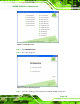
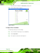

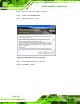


Table Of Contents
- 1 Introduction
- 2 Detailed Specifications
- 2.1 Dimensions
- 2.2 Data Flow
- 2.3 Embedded WAFER-945GSE Processor
- 2.4 Intel 945GSE Northbridge Chipset
- 2.5 Intel® ICH7-M Southbridge Chipset
- 2.6 LPC Bus Components
- 2.7 Environmental and Power Specifications
- 3 Unpacking
- 4 Connectors
- 4.1 Peripheral Interface Connectors
- 4.2 Peripheral Interface Connectors
- 4.3 Internal Peripheral Connectors
- 4.3.1 ATX Power Connector
- 4.3.2 ATX Power Supply Enable Connector
- 4.3.3 Audio Connector (10-pin)
- 4.3.4 Backlight Inverter Connector
- 4.3.5 CompactFlash® Socket
- 4.3.6 Digital Input/Output (DIO) Connector
- 4.3.7 Fan Connector (+12V, 3-pin)
- 4.3.8 Keyboard/Mouse Connector
- 4.3.9 LED Connector
- 4.3.10 LVDS LCD Connector
- 4.3.11 PCIe Mini Card Slot
- 4.3.12 Power Button Connector
- 4.3.13 Reset Button Connector
- 4.3.14 SATA Drive Connectors
- 4.3.15 Serial Port Connector (COM3, COM4, COM5 and COM6)
- 4.3.16 Serial Port Connector (COM 2)(RS-232, RS-422 or RS-485)
- 4.3.17 USB Connectors (Internal)
- 4.4 External Peripheral Interface Connector Panel
- 5 Installation
- 5.1 Anti-static Precautions
- 5.2 Installation Considerations
- 5.3 Unpacking
- 5.4 SO-DIMM and CF Card Installation
- 5.5 Jumper Settings
- 5.6 Chassis Installation
- 5.7 Internal Peripheral Device Connections
- 5.7.1 Peripheral Device Cables
- 5.7.2 SATA Drive Connection
- 5.7.3 Serial Port Connector Cable (Four Ports) Cable Connection
- 5.7.4 Dual RS-232 Cable Connection (w/o bracket) (Optional)
- 5.7.5 4-COM Port Adapter Board Connection (Optional)
- 5.7.6 Keyboard/Mouse Y-cable Connector
- 5.7.7 Audio Kit Installation
- 5.7.8 USB Cable (Dual Port without Bracket) (Optional)
- 5.8 External Peripheral Interface Connection
- 5.9 Heat Sink Enclosure
- 6 BIOS Screens
- 7 Software Drivers
- A BIOS Menu Options
- B Terminology
- C DIO Interface
- D Watchdog Timer
- E Address Mapping
- F Hazardous Materials Disclosure
WAFER-945GSE 3.5” Motherboard
Page 142
7.1 Available Software Drivers
NOTE:
The content of the CD may vary throughout the life cycle of the product
and is subject to change without prior notice. Visit the IEI website or
contact technical support for the latest updates.
The following drivers can be installed on the system:
Chipset
VGA
LAN
Audio
Installation instructions are given below.
7.2 Starting the Driver Program
To access the driver installation programs, please do the following.
Step 1: Insert the CD-ROM that came with the system into a CD-ROM drive attached to
the system.
Step 2: The screen in
853HFigure 7-1 appears.